In this blog post we look into some of Simcenter Amesim’s marine capabilities and review a comparison made between full-scale ship resistance simulation using CFD and predictions from Simcenter Amesim’s ship resistance models.
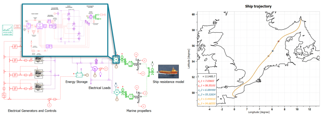
If a ship design’s hull resistance is determined, it is possible to calculate the necessary power required to propel a ship along a sea route. With the power requirements, an investigation into different types of propulsion systems can be carried out in order to assess a vessel’s overall (or instantaneous) fuel consumption, environmental impact, and investment cost. Insights gained from such an exercise can in turn be applied to retrofitting an older ship design or to constructing a new system altogether. As shown in the imagery above, various types of gensets, energy storage devices, and electric motors, can be connected, dimensioned, optimized, and finally evaluated along any sea route.
Working with a simulation tool in this manner offers several benefits. Multiple scenarios and routes can be crosschecked with different propulsion schemes to study trade-offs between concepts and designs. Component and system control strategies can be investigated and designed to meet the more stringent emission requirements by for example adopting a peak-shaving strategy where a larger battery is used to ensure more optimal combustion engine performance.
With Simcenter Amesim’s models for computing hull resistance it is possible to obtain a good understanding of a hull design’s resistance based on methods found in literature for similar designs. The calculated resistance can also be manipulated to study the impact of reduced resistance on the propulsion system due to a sleeker hull design. For shipbuilding a common practice is to employ CFD analysis or scaled model tests to determine a specific hulls resistance. This offers an advantage compared to working through resistance models since the envisioned hull geometry can be used directly and is likely to provide a resistance behavior closely matching the design. The results of such analysis may naturally be used in Simcenter Amesim to improve the predictions further.
How it works
The ship resistance submodel can be used to compute navigation translational resistance forces and ship translational dynamics when traveling along main sea routes and takes into account ship mass and the navigation resistance due to the friction with water.
If different sea conditions are to be studied, the ship resistance model can be combined with a variable sea conditions model. This model accounts for additional resistance caused by wind, waves and differences due to the variations in density and viscosity of water compared to reference conditions.
There are four ways to compute navigational resistance:
![]() Experimental data – ITTC 78 [1]: modeling based on the ITTC 78 procedure. The method is based on the extrapolation of model-scale tests and requires the availability of experimental data.
Experimental data – ITTC 78 [1]: modeling based on the ITTC 78 procedure. The method is based on the extrapolation of model-scale tests and requires the availability of experimental data.
![]() Statistical Barrass [2]: modeling based on the method presented in “Ship Design and performance for masters and mates” by Dr C.B. Barrass
Statistical Barrass [2]: modeling based on the method presented in “Ship Design and performance for masters and mates” by Dr C.B. Barrass
![]() Total resistance = f(v) – the total navigation resistance function of the ship velocity is read in a 1D table
Total resistance = f(v) – the total navigation resistance function of the ship velocity is read in a 1D table
![]() Holtrop and Mennen method [3]: modeling based on the paper “An approximate power prediction method” by J.Holtrop and G.G.J. Mennen. The method is based on the regression analysis of a vast range of model tests and sea trial data and requires detailed information on the vessel’s geometry.
Holtrop and Mennen method [3]: modeling based on the paper “An approximate power prediction method” by J.Holtrop and G.G.J. Mennen. The method is based on the regression analysis of a vast range of model tests and sea trial data and requires detailed information on the vessel’s geometry.
The full comparison between CFD simulation of full-scale hull models and the Simcenter Amesim approaches outlined above can be found in its entirety by searching for the demonstrator model titled “Navigation resistance and propulsion comparison” in Simcenter Amesim’s help section. In this post we content ourselves with reviewing the findings of the benchmark hull model KVLCC2. The hull model was originally developed for research and used in particular for validating CFD simulations. The model does not exist in full scale.
The comparison only makes use of the ITTC 78 and Holtrop & Mennen methods, and the description of the comparison below is the same as in the demonstrator model.
KRISO Very Large Crude Carrier 2
This ship is a benchmark hull model of a Very Large Crude Carrier developed by Maritime and Ocean Engineering Research Institute (MOERI). An illustration of the hull and its main features are provided below.
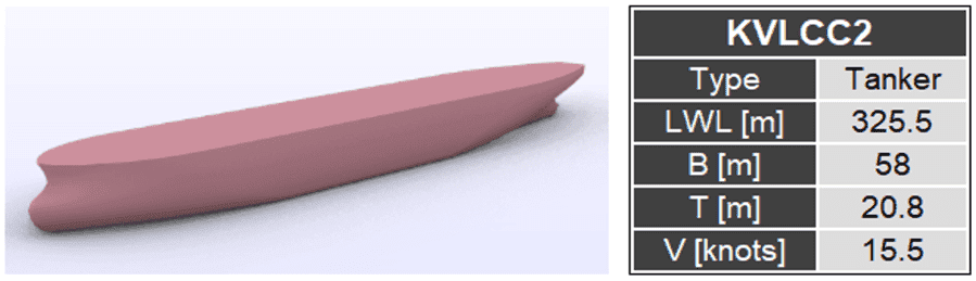
The geometric parameters and the CAD model of the hull and propeller were collected from the SIMMAN 2008 workshop [4]. The CAD model was used to obtain accurate values for the data that were necessary for a Holtrop and Mennen calculation, which included the waterplane area coefficient, the immersed transom area and the appendages areas. The value of the form factor was taken directly from the literature [5]. The wake fraction coefficient, rotative efficiency and thrust deduction coefficient were computed with Holtrop method.
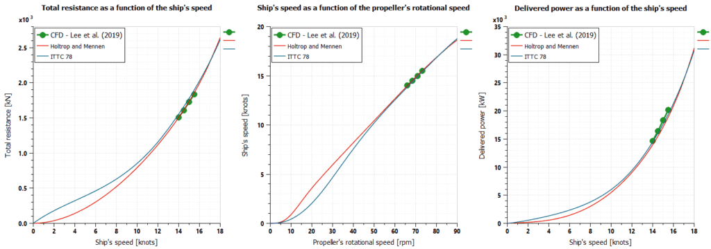
For validation of the model, experimental data for ITTC 78 was collected from [6] and full-scale CFD results were used for comparison. The CFD simulations comprised of four different values of ship’s speed. The figure below shows the simulation results, comparing them to the reference values.
The following tables present the comparison of the values obtained by Amesim and those from the full-scale CFD simulations, for each speed analyzed in the reference source.
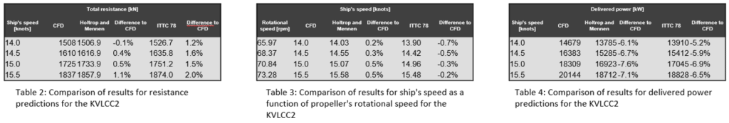
Comparing Holtrop & Mennen and ITTC 78 with the CFD findings, a difference of below 2 [%] can be seen for the total resistance calculated with ITTC 78, and below 1 [%] using the Holtrop and Mennen approach. For speeds above 10 [knots] both Holtrop and Mennen and ITTC 78 provide consistent resistance behavior and at lower speeds start to deviate from each other. Delivered power, calculated using a marine propeller submodel, shows differences below 8 [%] when compared to the CFD reference.
The comparison demonstrates that reasonable predictions can be achieved using only a limited amount of underlying geometrical information and proper estimates for parameters such as hull form coefficients, to which the resistance calculation is sensitive to.
Hopefully you found this post worth a look through. If you have any questions or comments related to the topic, or regarding simulation in general, please feel free to reach out to us by emailing support@volupe.com
References:
[1] International Towing Tank Conference, “Recommended Procedures and Guidelines”, 2014.
[2] Dr C.B.Barrass, “Ship design and performance for masters and mates”, 2004.
[3] J. Holtrop and G.G.J. Mennen, “An approximate power prediction method”, 1982.
[4] SIMMAN 2008. Workshop on Verification and Validation of Ship Manoeuvering Simulation Methods. Accessed at April 20th, 2021 [http://www.simman2008.dk/].
[5] Lee et al. Comparative Study of Prediction Methods of Power Increase and Propulsive Performances in Regular Head Short Waves of KVLCC2 Using CFD. 2019.
[6] Lee et al. Power Increase and Propulsive Characteristics in Regular Head Waves of KVLCC2 Model Tests. 2020.
Author
Fabian Hasselby, M.sc.
+46733661021
