The higher an uncertainty the more conservative a design. Eliminating uncertainties makes it possible to develop products which are safe, but not overly conservative in their design. This is why it is important to compute fluid loads on structures, rather than making highly uncertain assumptions about them. Luckily Simcenter STAR-CCM+ comes with an integrated solid stress solver which makes it straight forward to connect you flow simulation with finite element analysis.
My colleague Christoffer described How to set up a FSI simulation in Simcenter STAR-CCM+ with flexible solid that bounces on a wall in a Fluid Structure Interaction (FSI) with overset mesh setup. Just to refresh you mind,
- “FSI is when you have a two-way coupled interactions between a solid domain and a fluid domain. Pressure at the fluid-structure interface is computed by the fluid model, mapped to the structural model and applied as a pressure load”
Simcenter STAR-CCM+ offers:
- Explicit coupling of the models (data exchange occurs once every x units of time)
- Iterative coupling of the models (data exchange occurs multiple times per time step)
- For iterative coupling, solution stabilization methods are available including added mass pre-conditioning and displacement under-relaxation
The animation to the right shows an animation from a FSI benchmark (European Conference on Computational Fluid Dynamics ECCOMAS CFD 2006, EXPERIMENTAL STUDY ON A TWO-DIMENSIONAL FLUID-STRUCTURE INTERACTION REFERENCE TEST CASE, Hermann Lienhart, Jorge Pereira Gomes). The simulation was done all in Simcenter STAR-CCM+ in a single simulation (no co-simulation).
To follow the path on FSI, this blog article tackles FSI for Marine Propeller Simulation. Manly simulations that involve complex geometry and superposed motion of the propeller moving due to deformation and rotation. The test case is the Potsdam Propeller Test Case which is available among Simcenter STAR-CCM+´s tutorial files. In Automation of Marine Propeller simulation I describe how to automate the best practice for rigid body motion simulation which also could include an FSI coupling.

General setup
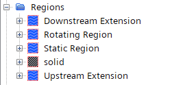
Starting from an uncoupled set up with a fully defined fluid and solid domain, Simcenter STAR-CCM+ allows you to define a general FSI analysis that accounts for two-way coupling. This means we can start from the final results of the MRF Marine Propeller in Open Water tutorial and utilize the fully developed flow. But is also means that we need a second solid domain of our propeller. STAR provides then a solution strategy with 4 major components:
- Exchange of Coupling Data (1-way or 2-way coupling)
- Data Transfer
- Consistencies
- Solution Stabilization
Data Transfer
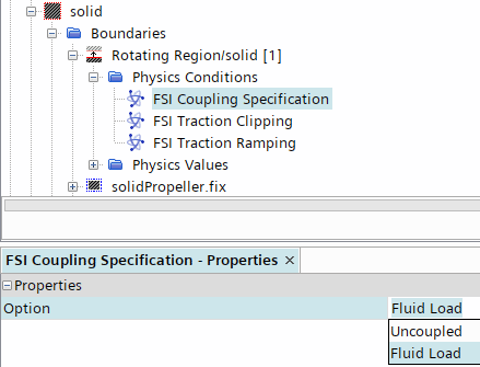
The information flowing from the fluid to the solid is the fluid traction. The fluid traction is automatically interpolated from the fluid side of the interface to the solid side where it is being applied as a load. In order to avoid the loss of information during the interpolation step you are advised to apply a similar mesh resolution on both sides of the interface. The interpolation scheme supports conformal and non-conformal interfaces which you create either from Weak in-place Contact or just by an Imprint operation at the beginning of your mesh operations.
Next, we need a physics continuum for the solid propeller. What you essentially need is the Solid Stress model as well as the material and Material Law Models. STAR can model Iso-, Aniso- and Ortho-tropic Material Linear Elasticity as well as Plasticity. But the PPTC should be fine with Isotropic Material.
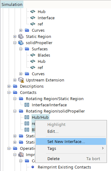
When the new region is assigned to the solid propeller we can create the Interface for the Data Transfer from the contacts (see above).
Consistency
In general the force consistency is an important part of an FSI simulation. This is achieve by Consistency of frames — meaning that both regions must use the same reference frame.
And Consistency of Interface Deformation — meaning that the mesh on both sides of the interface must deform in the same way. The key ingredient to get this propeller FSI working is the ability to superpose motions. In transient simulations, you can model rigid rotations and translations of the solid structure by prescribing corresponding mesh motions. When computing the solid displacements, Simcenter STAR-CCM+ accounts for the elastic deformation due to the inertia forces that arise from acceleration of the solid structure. The Superposing Motions allows you to add more rigid motions to Translation and Rotation motions such that our propeller can turn and deform due to fluid loads.
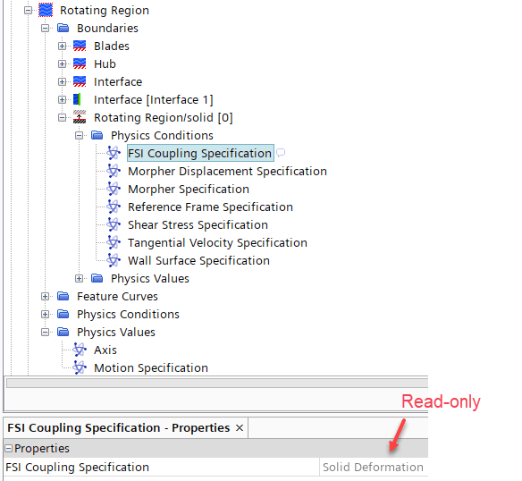
Beside the consistency requirement across the interface, be aware that the interface deformation is directly linked to the transfer of information from the solid to the fluid. Because of this dependency there is no explicit option to enable the coupling from solid to fluid. Instead the coupling of solid to fluid is implicitly controlled by the solid motion. For this reason the respective FSI Coupling Specification at the fluid region interface boundary is a read only property and is controlled by the motion of the coupled solid region.
For our propeller case this means we create a new Motions:
- Rotation
- Rotation -> Solid Displacement
- Morphing
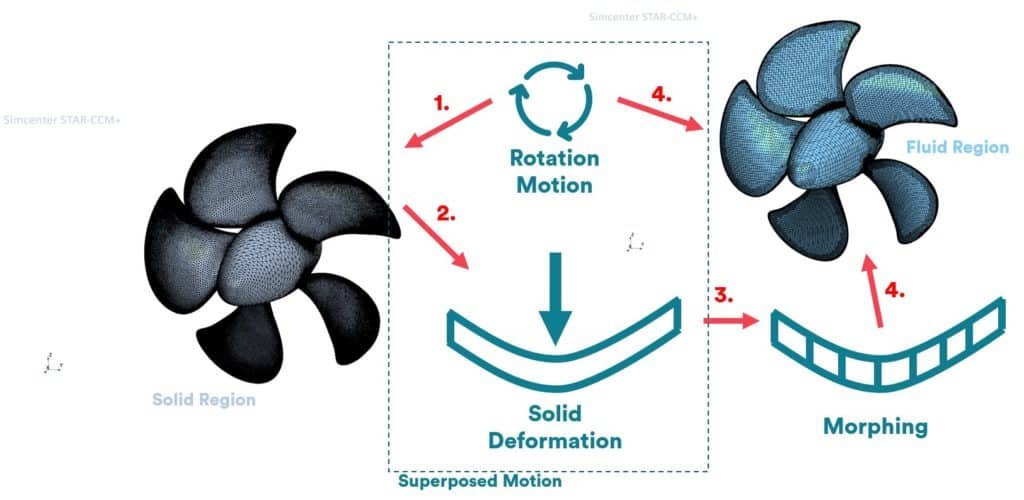
The Solid propeller is assigned with Rotation -> Solid Displacement Motion in Motion Specification. While the Fluid Propeller region is given the Morphing to take in the Solid Displacement. The rotation of the fluid propeller is eventually assigned to each boundary in Physics > Morpher Rigid Boundary Motion > Rigid Motion. This applies even for the internal Interface Boundary between the static and rotating regions. The Morpher Ridgid Boundary Motion becomes, however, only available by setting the Morpher Specification to Displacement at the corresponding boundary. The boundary vertices are moved by a specified distance. In our case Increment adds Linear displacement of boundary vertices relative to the vertex positions of the previous time-step or iteration. There are several types of displacement types available in Morpher Displacement Specification node, from which you can select further options for displacing the boundary vertices.

Solution Stabilization
Set up the solvers according to best practice. For instance for a the implicit unsteady solve select a sufficient time step. Possibly start with an advancement of 5 degrees per time step after the flow developed with MRF propeller. For the Fluid Structure Coupling Simcenter STAR-CCM+ offers two different methods for solution stabilization — Boundary Interface Added Mass and Constant Displacement Under-relaxation. Both methods are only available for transient cases.
The purpose of the Boundary Interface Added Mass is to increase the performance of the FSI simulation by predicting the fluid tractions resulting from the change of the interface position. It is assumed that a certain volume of fluid moves with the FSI boundary acting as an added mass. This method is recommended for two-way coupled problems.
One-Way Fluid to Structure Coupling
The simplest way to uncouple the above described setup would be to change the Motion Specification from Morphing to Rotation. This way we still evaluate the stress from the fluid load by the solid stress solver yet don´t feed back the deformation. However, this still requires the computation of loads at each time step.
Another more efficient option would be to solve the fluid and the structure sequentially instead of simultaneously. This approach allows you to record a transient flow solution and to reuse the recorded fluid loads, recorded in a simulation history file, in multiple stress analyses without rerunning the flow solver.
Results
The PPTC tutorial setup can be converted into 2-way FSI simulation, even if the general concept of having an unsteady FSI for an open-water analysis is rather pointless. You get the idea of using the developed flow as a starting point. The most common problems that might rise are most likely related to insufficient interface as result from too different mesh resolutions between the solid and the fluid representation. However, the simulation can also be run without MRF initialization. This way you can automate the analysis at different operation points, as show in the video below.
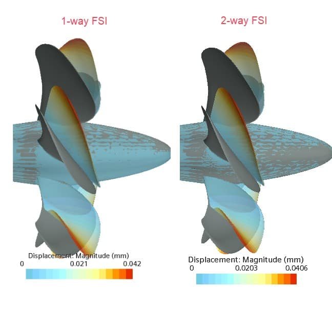
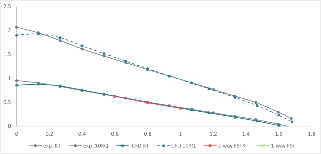
Comparing the results between 1-way and 2-way couple FSI we can see a difference of 6% displacement magnitude and below 2% in KT and maximum von Mises Stress. Comparing the 2-way FSI results with the experiments and pure fluid analysis show very little difference and this is not supposed to be a quantified comparison either.
The integrated FSI setup in Simcenter STAR-CCM+ allows us to predict the performance of system or components exposed to fluid flow which is key for the innovation of such products. Another example can be the hydro foil of a catamaran which lifts the catamaran out of the water, so that the catamaran can glide with less resistance through the water. The fluid loads acting on the foil will deform it, and that will impact the performance of the foil. Therefore the modelling of the fluid-structure interaction is key for innovation and gives you more insight into your design.
The Author
Florian Vesting, PhD
Contact: support@volupe.com
+46 768 51 23 46