In this week’s blog post we will demonstrate the different options you have to split faces inside the 3D-CAD module in STAR-CCM+. The need for splitting faces could be for e.g. post-processing purposes or perhaps for splitting boundary conditions on specific boundaries. The 3D-CAD module in Simcenter STAR-CCM+ offers a number of possibilities to achieve this.
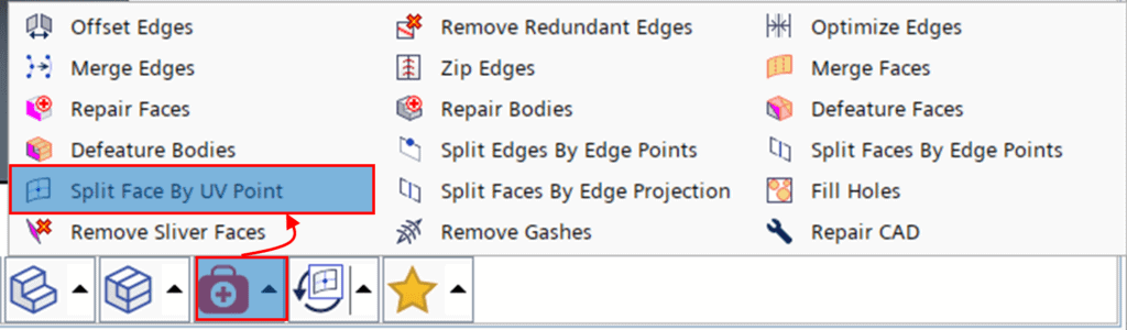
Option 1 – Split Face By UV Point
All splitting functions can be found inside the Repair Feature tool, found on the bottom of the scene view (see picture below). The first option we will demonstrate is the feature “Split Face By UV Point”.
As you might already suspect, the abbreviation UV has nothing to do with light waves, but rather refers to two cross-directional curves denoted U and V. The way this feature works is that it identifies two orthogonal perimeters (U and V) on your surface of choice and discretizes the lengths of these perimeters. The lengths are normalized, and you specify a value between 0 and 1 where you wish to perform a split of the surface. You have the possibility to make a split in either U-direction, V-direction or both. Below is a short video clip demonstrating how to use this feature on an arbitrary free-form shape.
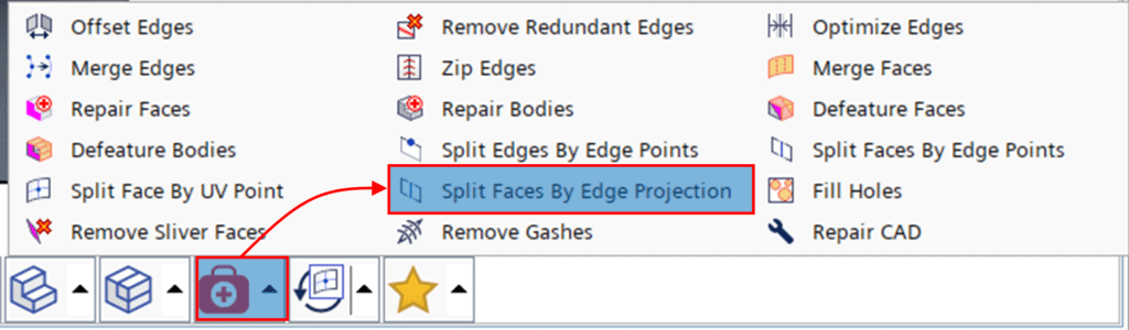
Option 2 – Split Faces By Edge Projection
The second option is to use the feature “Split Faces By Edge Projection” (see feature location in the picture below). This feature is perhaps close to self-explanatory, since it simply splits faces by projecting edges of choice onto user-specified faces.
The usage of this feature has actually already been demonstrated in a previous Volupe blog post and can be found through the following link:
Geometry preparation in 3D-CAD within Simcenter STAR-CCM+ – VOLUPE Software
Please refer to “Video 2” for demonstration of this feature.
Option 3 – Split Faces By Edge Points
The third option is to use the “Split Faces By Edge Points” feature (see picture below). This feature allows you to position reference points on edges that interconnect through a curve along the surface. The surface may then be split using this curve.

Below is a video clip demonstrating how this feature can be used.
Option 4 – Sketch Imprint
In addition to the options available in the Repair Feature tool, 3D-CAD offers the possibility to imprint sketches onto faces (or bodies). Similar to Option 2, this feature projects curves onto user-specified faces, but rather than using face or body edges the input is a sketch. To use this feature, you right-click the sketch of choice and select “Sketch Imprint” (see picture below).

An example of how you can utilize Sketch Imprint is demonstrated in the following video clip.
I hope you find these features useful in your geometry preparation work. As always, if you have any questions or comments you are welcome to contact us through support@volupe.com.
Author

Johan Bernander, M.Sc.
+46 702 95 18 31