A common recommendation when running CFD simulations is to position your boundary conditions far from your area of interest, to not influence the results through stiff numerics. But sometimes this can be difficult (or computationally expensive) to achieve. A common challenge is the pressure outlet, which typically acts as the environmental or far field pressure reference. The default setting for a pressure outlet boundary is a constant value of relative pressure, but in many cases this might not be representative for the real conditions you’re trying to replicate. In this week’s blog post we will go through the different options and settings available for the pressure outlet boundary condition in Simcenter STAR-CCM+, which lets you adjust the characteristics of the boundary condition to better reflect the real conditions. The settings we will investigate are found in the “Physics Conditions” folder of any pressure outlet boundary.
Backflow Specification
The first setting to consider in the Physics Conditions folder is the Backflow Specification. As may be understood by the name, this is where you specify the characteristics of any flow that may re-enter your domain through the outlet boundary. Three settings are available for the Backflow Specification; Direction, Pressure and Scalars. We will now explain the different options below.
Direction
There are four different options for specifying the flow direction of the incoming backflow through the pressure outlet boundary (see picture below).
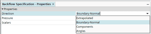
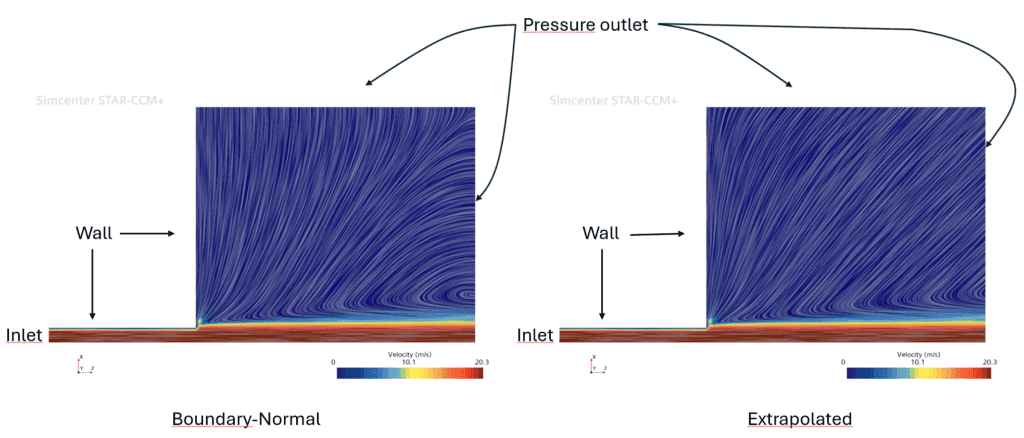
- Extrapolated: As the name implies, this setting extrapolates the direction of flow from the interior cells. This setting allows for the reversed flow to adapt to the interior flow conditions. It is typically recommended for cases where you expect flow to run parallel to the outlet boundary. One such example could be a jet exiting from a nozzle into atmospheric conditions, as depicted below. The leftmost picture uses Boundary-Normal and the rightmost picture uses Extrapolated backflow direction. The Extrapolated option is the default option for the Coupled solver but is generally a bit more unstable than the Boundary-Normal option.
- Boundary-Normal: Assumes that any backflow re-enters the domain normal to the outlet cell face, regardless of the interior condition. This is the default option for the segregated solver and is generally very robust. It may obviously not always be the most physical approach though.
- Components: Allows the user to explicitly specify the direction of inflow using vector components.
- Angles: Allows the user to set the backflow direction using Euler angles, i.e. a composition of rotations of a unit vector around certain axes of a reference coordinate system.
Pressure
Two different options can be used for the pressure specification, Static and Environmental (see picture below).
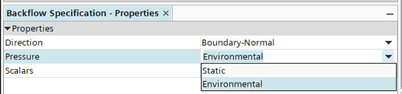
The difference between these two is that the Static option maintains the pressure at the explicitly specified value regardless of any backflow, while the Environmental option subtracts the dynamic head from the specified pressure value, hence accounting for pressure loss due to re-entering flow.
Scalars
The Scalars setting also has two options, Specified and Extrapolated. The Specified option means that the scalar quantities that you specify under Physics Values (e.g. temperature) are used regardless of the interior flow conditions. The Extrapolated option, however, extrapolates scalar values from the adjacent cells on the interior to the outlet boundary.

Pressure Outlet Option
In some cases it might not make physical sense to explicitly specify a constant ambient pressure on the outlet, or be difficult to use e.g. a table or field function to adapt the pressure across the boundary to fit the conditions at hand. The Pressure Outlet Option node allows you to adapt the outlet pressure across the boundary to better fit the physical conditions of your case. There are several options that you may want to consider (see picture below).

- Non-Reflecting: This option prevents unphysical numerical reflection of the solution back into the domain by applying the specified pressure as an average quantity and allowing for e.g. acoustic waves to exit the domain.
- Target Mass Flow: The Target Mass Flow option uses a correction approach to the user-specified pressure on the outlet boundary to achieve a specified target mass flow. This option is typically used along with a stagnation inlet. The recommendation from Siemens is to NOT enable this option from start of the simulation, but rather start with a developed flow field using a qualified guess on the average outlet pressure. The solution approach for the pressure correction is to adjust the outlet pressure at a user-specified increment of iterations, until the target mass flow has been acquired. There is a well-documented example of how to use the Target Mass Flow option available on Siemens Support Center; What is Target Mass Flow option in Pressure Outlet boundary ? (siemens.com)
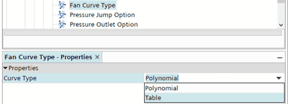
- Pressure Jump: This option can be used to account for known and well-described downstream effects such as shape changes (for internal flows), fans or restrictive geometries (e.g. porous zones) without explicitly including these features in the simulation domain. Activating this option allows you to specify a pressure change as a function of flow across the boundary by mathematically mimicking these types of features.
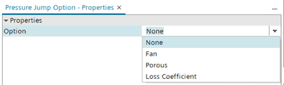 The pressure change for a fan pressure jump is modelled using a fan curve, either with tabulated values or using a polynomial. The fan curve input data is given in the Physics Values folder once the pressure jump options are set up in the Physics Conditions folder.
The pressure change for a porous pressure jump is modelled through the specification of inertial and viscous resistance terms.

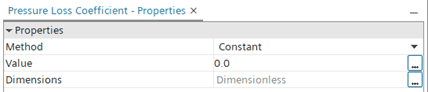
You may also define your pressure jump formulation with a loss coefficient, based on e.g. empirical data.
- Average Pressure: This option adjusts the pressure profile of the closest cells to the outlet boundary so that the average pressure in these cells equals the specified average pressure on the outlet. Using this option will hence allow for a pressure gradient on the outlet boundary and a system that is less stiff.
I hope this blog post was helpful to showcase the possibilities you have for your pressure outlet boundaries. If you have any questions or comments you are always welcome to send them in to support@volupe.com.
Author

Johan Bernander, M.Sc.
support@volupe.com