Euler angles and Tumbling of badminton shuttles in Simcenter STAR-CCM+
We are back with badminton related simulations on the Volupe blog and this time we will focus on tumbling shuttles. Tumbling is a phenomenon where the shuttle is spinning heavily, and the rotation needs more than one axis to describe the motion. Tumbling motion occurs when the initial forces and the body forces (fluid and gravity forces) cannot (quickly) find a stable rotation around the axis through the center of pressure and the center of mass, giving rise to a chaotic search for equilibrium of force. This was described in a previous blog post: https://volupe.com/simcenter-star-ccm/turning-of-badminton-shuttles-and-flexible-dfbi-set-up-in-simcenter-star-ccm/
A comparison with new simulations for tumbling net shots with a corresponding video of the actual net shot (experimental results) will be discussed in this post. This is performed for several moments of inertia (MOI). Where one of the MOI is from a new study performed at Chalmers [1].
But to get a better understanding of how to measure orientation of rotating bodies we first need to dive into Euler angles and how they are treated mathematically as a transformation and in Simcenter STAR-CCM+. This way of measuring angles will then be used to generate data which can be compared with the experimental results.
Euler angles – definition
Use of Euler angles is needed when you have a rotation that happens around several axes [2]. Since angles are non-commutative (meaning a+b is not equal to b+a), describing the rotation needs to happen in a certain order. Hence, we need a convention to follow. Note that small angles (up to some degrees) are commutative, but for the general case this is not true.
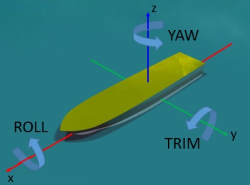
Proper Euler angles rotate around the local Z-axis, then the shifted X-axis and after that the newly shifted Z-axis. There is also a similar convention called Tait-Bryan where you rotate around the local X and Y and Z axis, where the axes are called roll, pitch and yaw (pitch angle is called trim in marine applications, see picture below, from Siemens support center [3]). The order of which axis to rotate around first can be chosen based on preference, but most common is the convention described here.
This means that when you want to find out the new orientation of an object based on measured angle values, you start from the initial position and orientation and rotate the body in the Euler angle convention order that was used based on the global coordinate system. In the case above that would correspond to rotation around X then Y then Z. If you prefer to rotate the coordinate system together with the object, you have to perform the rotation in reverse order and the coordinate system would be rotated as well. In the case with X-Y-Z convention you would then start rotating around the global Z-axis, then the new Y-axis and at last the newly shifted X-axis.
Euler angles – in Simcenter STAR-CCM+
In Simcenter STAR-CCM+ the more common Tait-Bryan angles are used. It is recommended for most applications to use X-Y-Z convention. One thing worth mentioning is that if you want to compare rotations you need to compare values of rotation that has used the same convention.
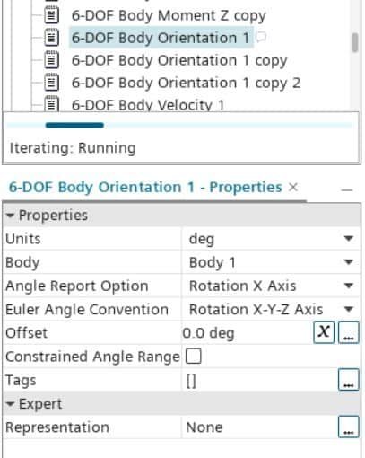
In Simcenter STAR-CCM+ the DFBI-orientation-report will ask for an Euler convention and an axis to measure, see picture below where rotation around the X-axis with convention X-Y-Z is measured. And the angles will be measured from the Global coordinate system origo and axes. So in order to measure the rotation of a badminton shuttle we need three reports for orientation, one in each direction X, Y and Z.
Note that the constrained angle range option (not used in this example) enables the angles to be measured from -180 degrees to 180 degrees. When an angle becomes larger than 180 degrees in absolute value it is shifted by 360 degrees to fall into the interwall again (giving a jump in the report graph). This will ensure reported values will not become too large if several full rotations occur.
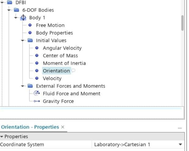
In the initial values for your DFBI-body you can specify how the position of the body coordinate system will be defined. The center of mass (COM) defines the origin on your DFBI-body’s local coordinate system. In the picture below you see that a local coordinate system is used to specify the initial condition for orientation of the shuttle. You can specify the initial values in the global coordinate system but usually it is easier to use a local coordinate system, and a recommendation is to specify all initial value in the same coordinate system. The initial values for position (COM) and orientation together specifies how the local DFBI-body coordinate system is defined in respect to the body. This local coordinate system is created together with the DFBI-body and is found in Tools -> Coordinate systems. Note that you modify the DFBI-body coordinate system by changing values in the DFBI node. Additionally, you cannot specify initial conditions in the DFBI-body coordinate system since the definition must be in another coordinate system.
If you want a local coordinate system, that is not the DFBI-body’s coordinate system, to follow your DFBI-body, you create a new coordinate system as a local coordinate system under your DFBI-Body coordinate system. There is also the possibility to create a follow-motion by right-clicking on the DFBI-body node where you can set a coordinate system as Managed, but this will be more computationally demanding since the follow motion needs to be calculated.
Experiment setup – tumbling of a shuttle
Previous blog posts related to badminton have focused on the trajectory of the shuttle and the turning point of when the shuttle hits the racquet. Now we combine these two phenomena into a tumbling net shot.
In the video below you see the tumbling that has been simulated. Big thanks to my friends Tony Hansson and Liam Kosterhed for great net play which made it possible to find a good strike to imitate in the simulations.
Simulation results – orientation of the shuttle
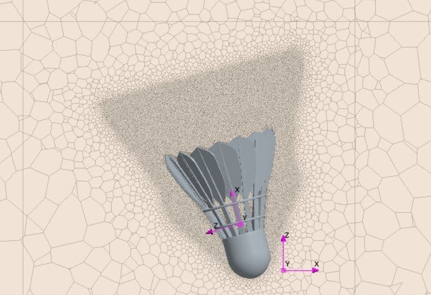
Tumbling shuttles are even more sensitive to initial conditions and DFBI properties then previous simulations, since equilibrium for all forces is found late in the trajectory. This made the simulations more prone to diverge and the results differ more compared to the experiment. Small time steps, of 1e-5s needed to be used instead of 5e-5s. Additional mesh refinements were also added. Since the rotation is large in the beginning and forces from the racquet are difficult to measure, the initial conditions had to be approximated from the video – where initial velocities and rotational speed in all directions were observed and set. All values were defined in the local coordinate system, [10, -40, 200] radian/s and [8, -0.5, 0.5] m/s was used for initial rotation and velocity. See picture below for mesh resolution and local coordinate system to the left (at the shuttle) and global coordinate system to the right.
Previously two different sets of MOI have been used in simulations and this time we added a new set of MOI from Chalmers latest study. The values of MOI are described in the bullet point list below and they are defined in the local coordinate system.
- LIN: 1.39e-6, 3.32e-6, 3.32e-6 [m]
- Chalmers (new): 1.91e-6, 2.97e-6, 2.97e-6 [m]
- Cooke: 1.16e-6, 2.87e-6, 2.87e-6 [m]
In the video below you find the three tumbling net shots, which are all quite similar. Even though the MOI differs a bit, especially in I_xx values.
To be able to compare positions and rotations of shuttles we need to extract values from the simulations. As mentioned before, all angles are measured in the global coordinate system. In an ideal comparison we would also be able to measure rotation of the experiment in order to have a true value to measure diviation from, but that is still something we have to perform as a further study, and for now we need to rely on observation of the video.
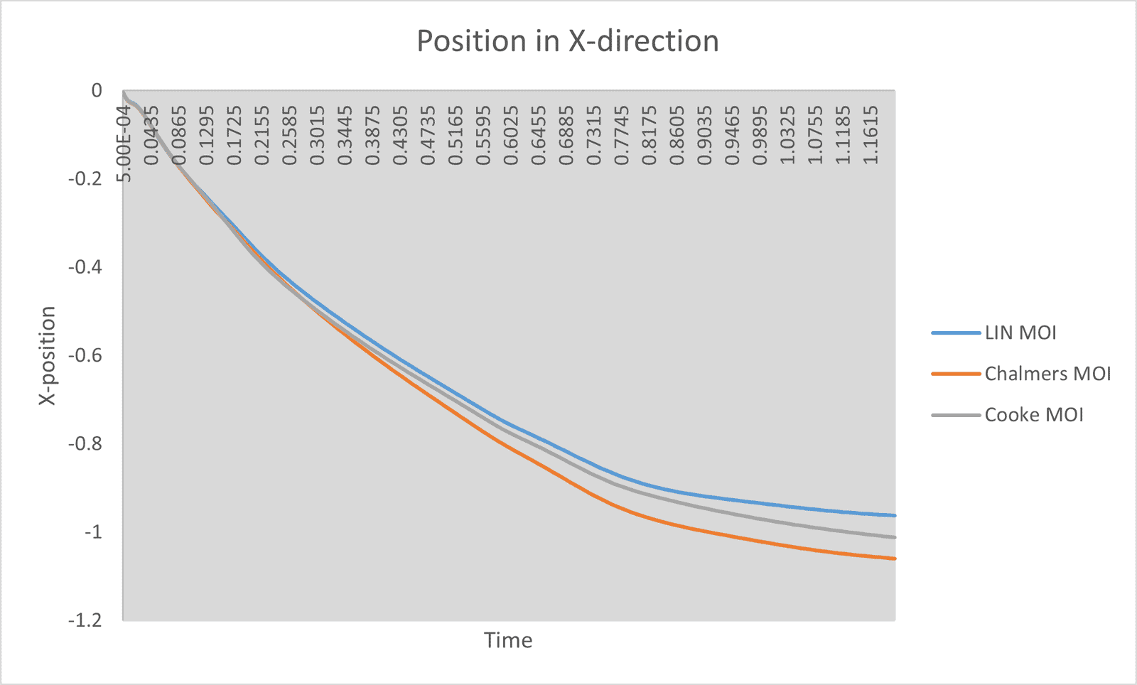
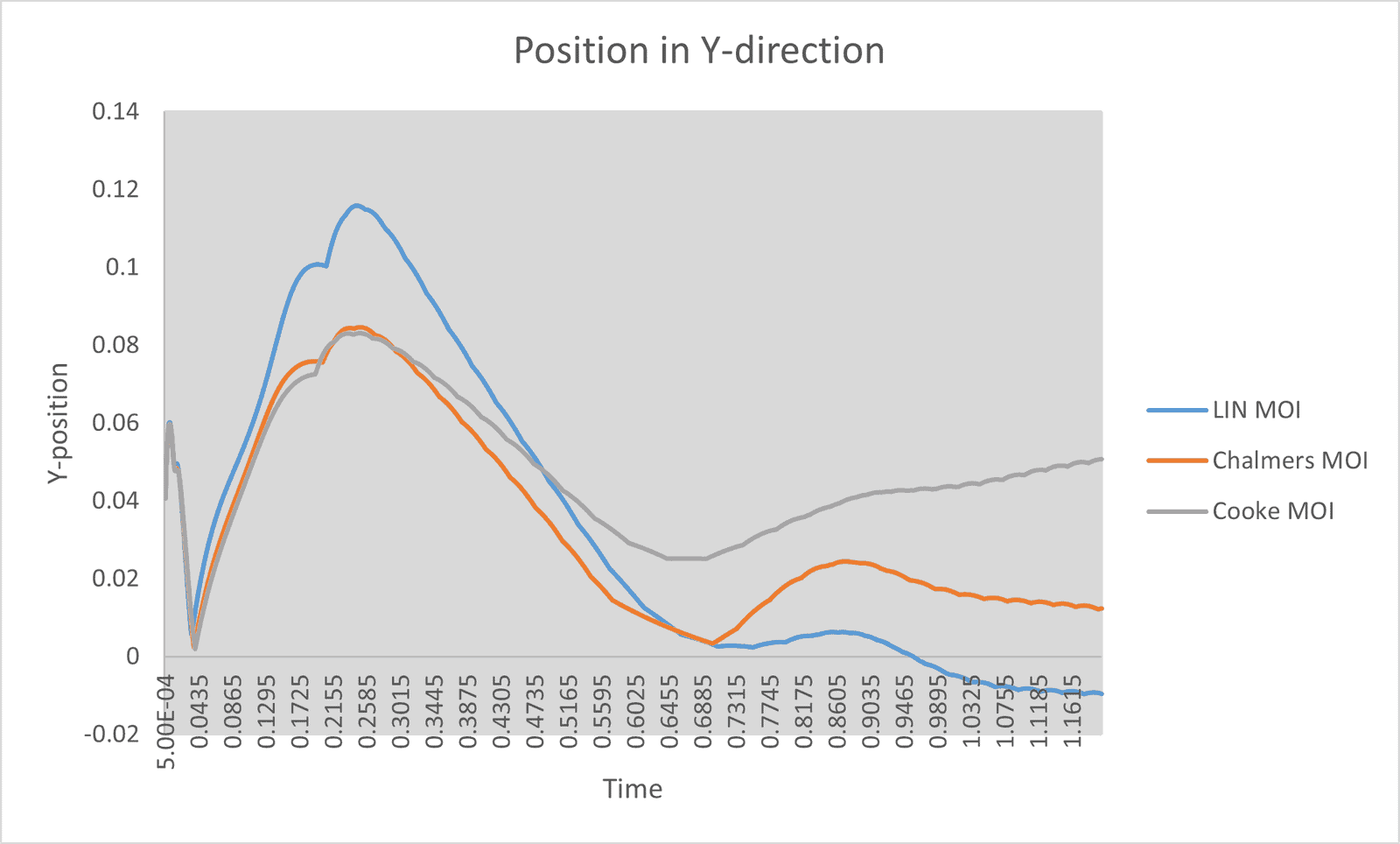
Extracting the position and orientation values for the tumbling shuttle we see that Y-position differs most between the simulations. The turning points for orientation in Y-direction differ slightly for the different MOI, which is worth noticing. Using MOI from Lin’s results correspond to highest absolute values in deviation for trajectory values in Y-position and the most fluctuating values for rotation around the Y-axis.
Position in X-direction starts from zero goes towards negative values in the global coordinate system.
Y-position for the shuttle is more dependent on MOI than other tumbling parameters. Largest flucutations occur for Lin’s MOI.
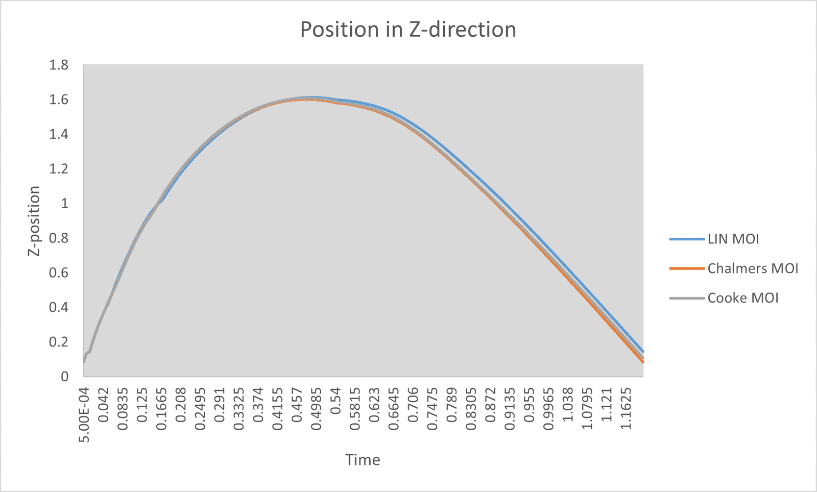
The height (position in Z-direction) of the trajectory corresponds well between the simulations, which is expected since the tumbling does not effect the trajectory i Z-direction to large extent (especially since the flight paths are this similar).
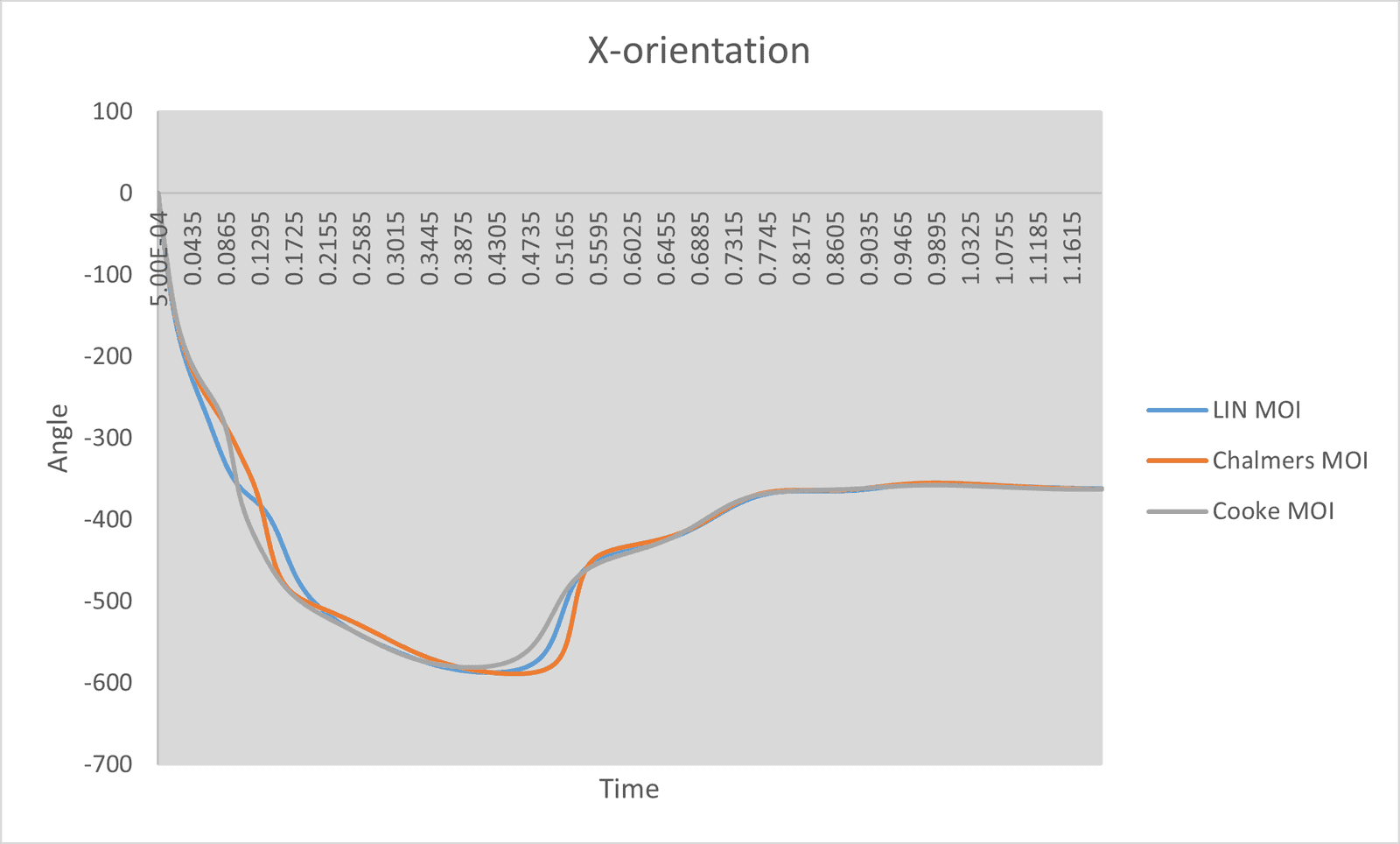
Orientation in X-direction shows that the initial rotational speed is high, since the values change rapidly. Halfway (at the highest point of the trajectory) the rotation changes direction and in the latest part of the trajectory there is no change in X-orientation for the shuttle. In the experiment the shuttle rotates two full turns (720 degrees) but in the simulations the shuttle stabilizes earlier.
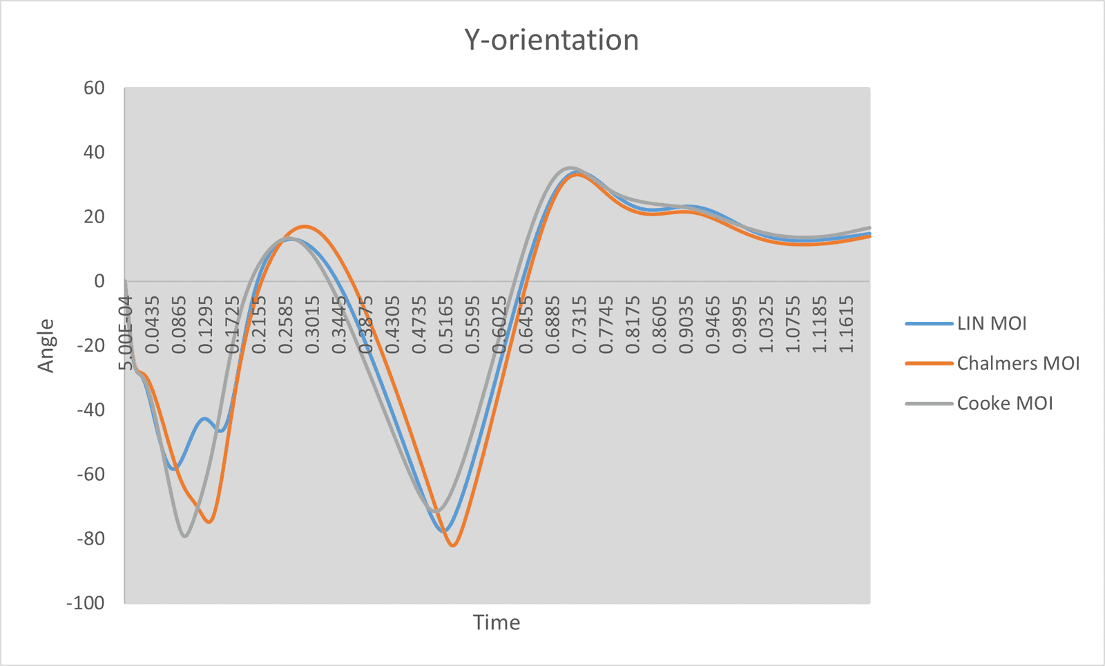
The Y-orientation shows that the shuttle fluctuates back and forth in order to find the equilibrium orientation. In the experiment the shuttle is pointing upwards with the cork at the highest point of the trajectory, but in the simulations a stable flight path with the cork most forward (in the direction of the DFBI movement) is already established before the highest point in Z-direction. In the experiment the absolute values of Y-orientation would go up to 180 degrees and only change direction once, but in the simulations the absolute values are lower and change of direction occurs twice.
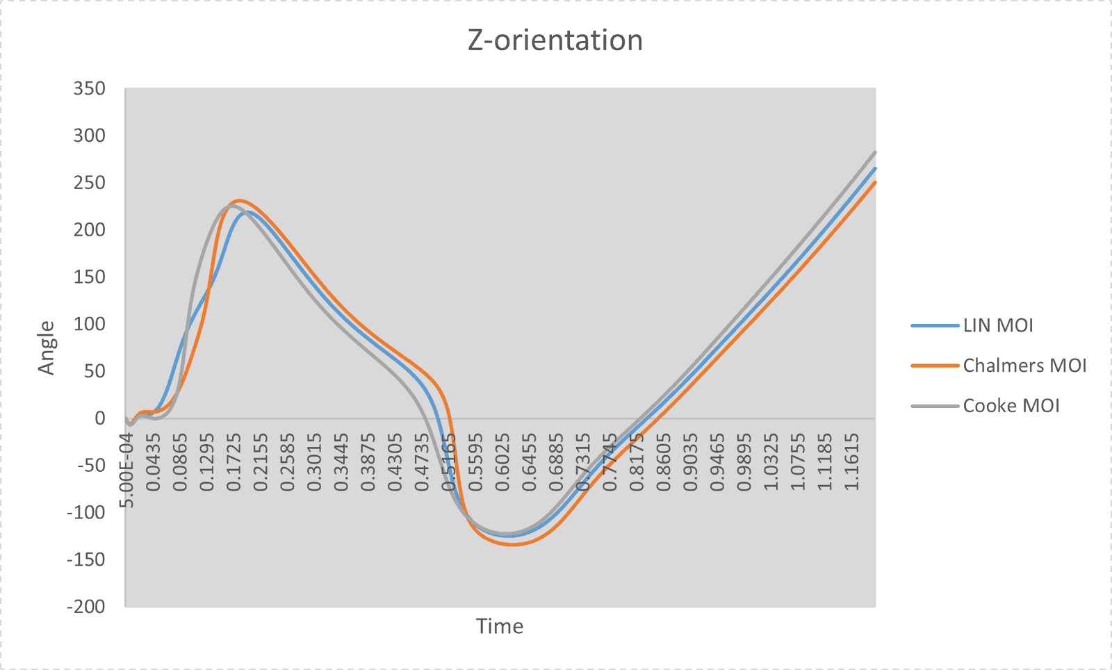
The orientation in Z-direction indicates which direction the cork is pointing (up or down), since the rotation around the symmetry axis is always the same (due to the feather positioning). In the end almost all rotation happens in positive Z-direction, with the cork pointing downwards. At this point the other orientations have stopped changing values.
For Z-orientation, comparison with the experimental video is difficult since rotation around the symmetric axis is goes fast and is not as easy to see in the video. Increase values in the later part of the flight agrees with expectations, since the rotation increases around the symmetry axis, but to perform a deeper analysis than that we need raw data from the experiments to compare with simulation results.
Conclusions
Comparing the experimental video to the simulations we can see that the fluctuations in orientation are higher in reality. Even though the spinning is rapid in the beginning, both for the experiment and the simulations, the shuttle continue to tumble longer in the experiment. Over all the simulations capture tumbling quite well, but this descepancy that simulations find a less chaotic rotational state faster needs to be investigated further. Additionally, the range of values for MOI that is used is quite wide, still the difference in simulation results is small, which indicates that the impact of MOI input needs to be investigated further as well. The phenomenon of tumbling is complex, and the simulations seem to struggle to get the exact trajectory and rotation of the shuttle. At the moment is it difficult to draw conclusions on which MOI provides most realistic results, but Lin MOI provides slightly more fluctuations which is what the simulations have struggle to predict, and therefore Lin MOI will be used in future studies.
Bibliography
[1] K.Aadland, M.Frogemar, N.Granerås, L.Larsson and M.Manne (2025). Ballistik och aerodynamik av badmintonbollar. Chalmers ODR, https://odr.chalmers.se/items/b241abb9-93ac-4a8e-b585-e7bc563543e6.
[2] Wikipedia (2025). Euler angles. https://en.wikipedia.org/wiki/Euler_angles.
[3] Siemens (2021). What is the Euler Angle Convention? An example of how to compute the roll, trim and yaw for marine applications. https://support.sw.siemens.com/en-US/product/226870983/knowledge-base/KB000031444_EN_US?pid=resource&pid_context=Related&audience=external
Thank you for reading this blog post, we at Volupe hope that it has been both interesting and informative. Rotation and orientation in Simcenter STAR-CCM+ have several ways to be expressed, and can be difficult to grasp, but the topic is hopefully clearer now. If you enjoyed this post, keep an eye out for more badminton related blog posts in the future. As always, you are more than welcome to reach out to us at support@volupe.com if you have any questions.
Author
Christoffer Johansson, M.Sc.
support@volupe.com
+46764479945