The Challenge of Working with Legacy CAD or Scanned Hull Forms
Anyone who has worked with 3D scanned data or dead CAD geometry knows the frustration: intersecting facets, irregular tessellation, and surface quality issues that make traditional CAD manipulation nearly impossible. When customers provide scanned hulls from existing vessels, the resulting geometry often looks messy and unusable for design exploration.
Morph Surface Mesh: Two Morphing Modes
Simcenter STAR-CCM+ 2506 offers now two distinct morphing approaches to morph (deform) a surface mesh based on an input that you supply. The resulting surface is stored as a new description for the selected input parts.
- Field Function-Based Surface Morphing
This mode is recommended for shape optimization applications involving large deformations. It allows spatially varied deformations based on the supplied displacement field. When evaluating the displacement field on the volume mesh, you can use the surface morpher in the Adjoint solver operation loop to optimize the design by morphing the surface based on a field function.
This makes it ideal for cases where the morphing should respond to flow characteristics. But it can also be used when you need to mathematically define an initial shape using field functions applied directly to the surface mesh.

- Parametric Surface Morphing (new)
The parametric surface morphing method changes surface shapes by controlling their parameters directly. By using specific design variables, this approach is ideal for design optimization. It generates a new Surface Mesh Description from given parametric translations or rotations, enabling smooth, automated design studies. The parametric strategy also guarantees repeatability and supports efficient exploration of different design possibilities.
Direct Parametric Manipulation of Tessellated Surfaces
The new parametric surface morpher changes this concept entirely. Instead of requiring clean CAD geometry, it works directly with tessellated surfaces. The workflow is remarkably straightforward:
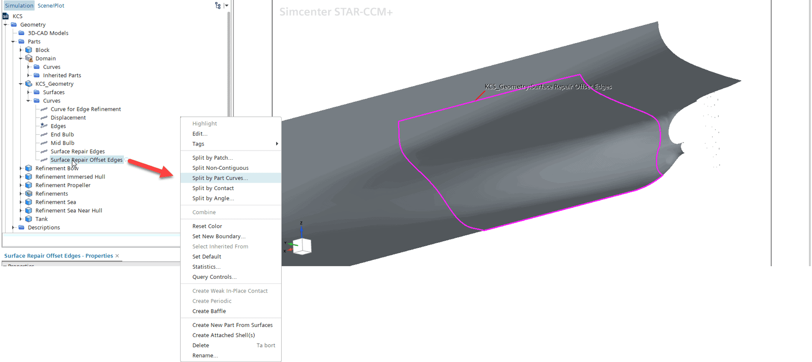
- Isolate target surfaces: This can be done on a tessellated surface with Surface Repair tool in STAR-CCM+.
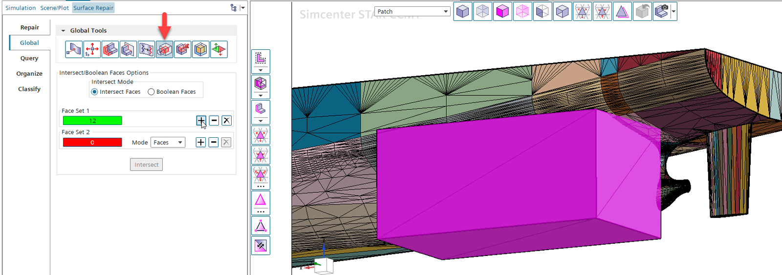
- Create a Shape Part that encloses the area that shall be floating

- Select both to be opened in Surface Repair tool and use the Global > Intersect/Boolean Faces tool for intersecting the surfaces.

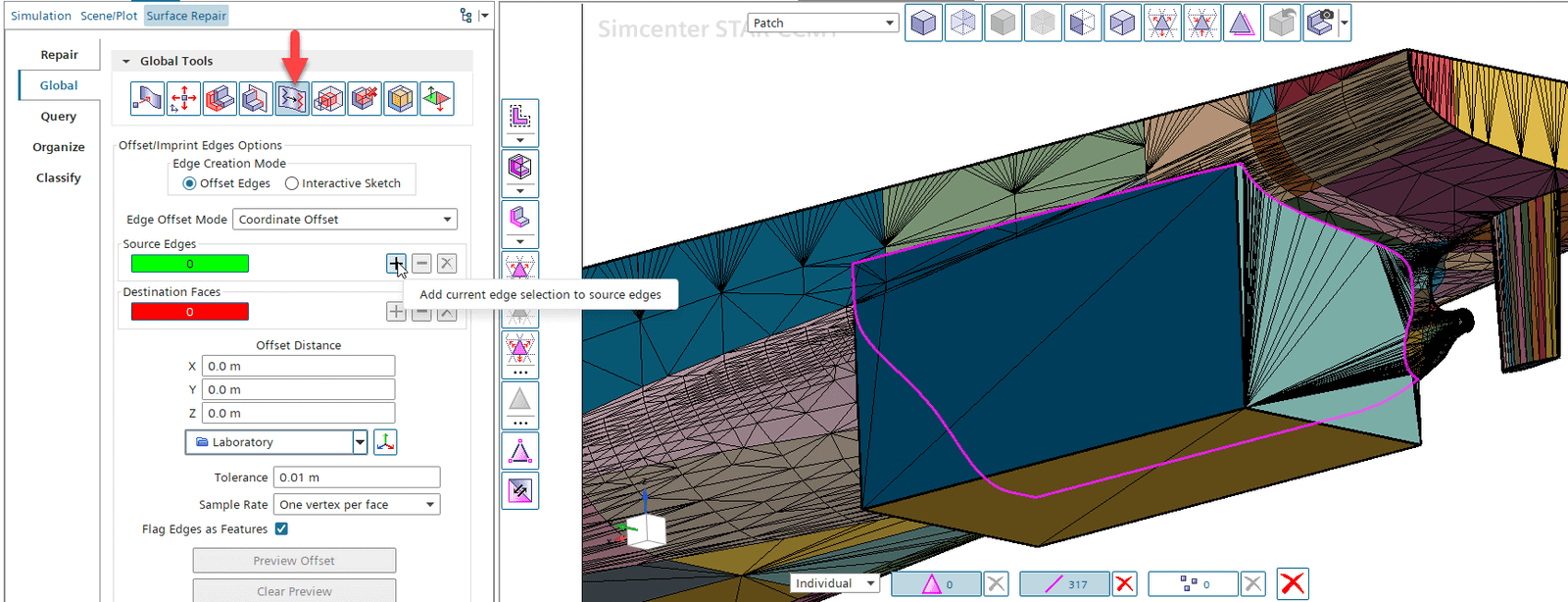
- This will create a new edge along the intersecting surfaces. While the selection is still active, switch tools to Global > Offset/Imprint Edges for imprinting the edge on the hull surface.

- Now we can split the hull surface by Part Curve

- Create a Shape Part that encloses the area that shall be floating
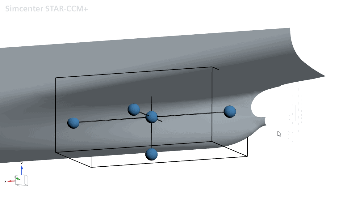
- Create edges for displacement: To create an edge e.g. in the middle of the floating surface, we can use the Surface Repair Offset/Imprint tool again with an Interactive Sketch. This is outlined in detail here:

- Define displacement parameters: Specify translation vectors or use global parameters.
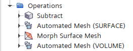
- Set morphing conditions: The noticeable point of this setup is that you have to split your Automated Mesh Operation into two parts: one containing the Surface mesher(s) only and the other one the Volume mesher(s) only. The Morph Surface Mesh Operation will be inserted in the middle:
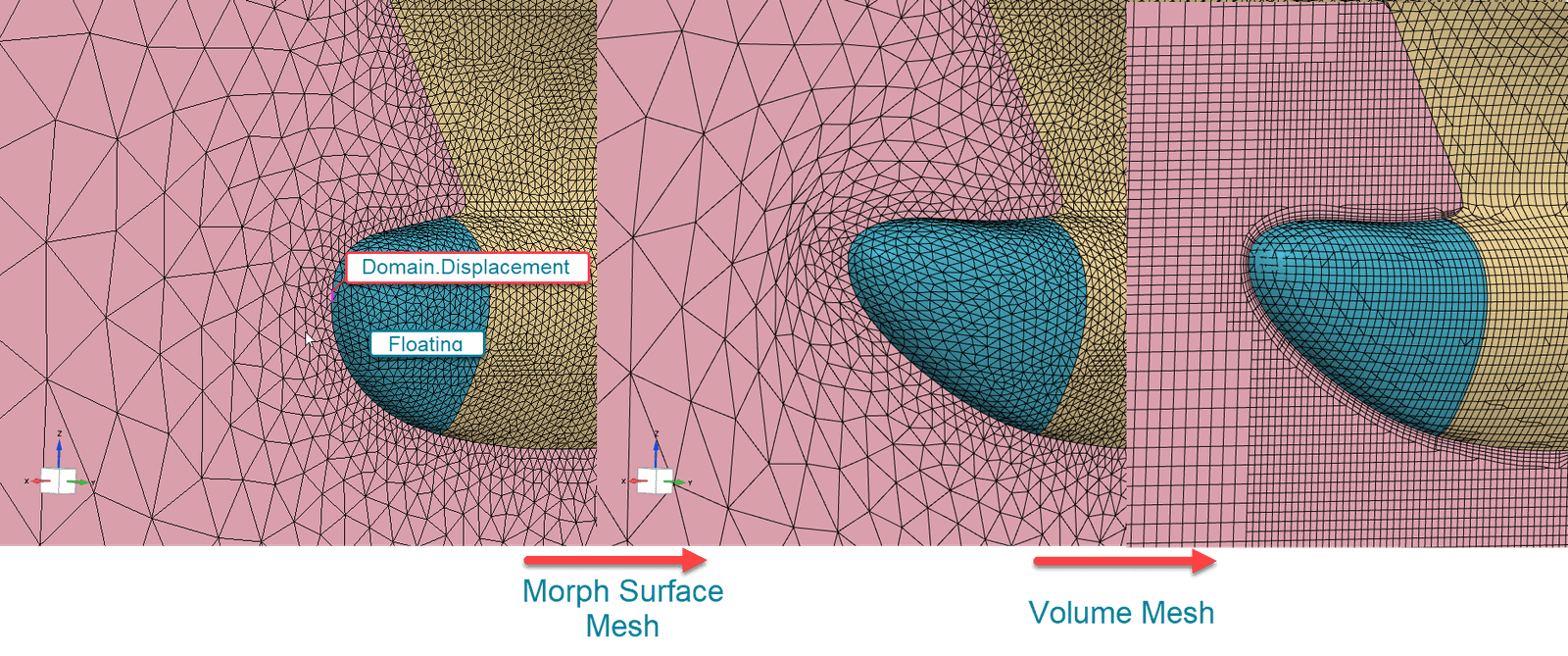
 Provide created edge as the designated “Displaced Part Curves” and the section of the hull as Floating Part Surfaces that stretch to accommodate changes.

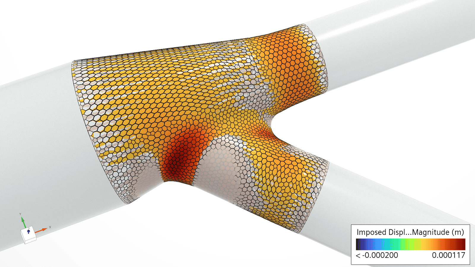
- Execute the morph: Watch as the surface deforms parametrically while maintaining topology the morphing operation is surprisingly fast, typically completing in 2-5 seconds even for detailed external aerodynamics cases, depending on the number of surface triangles involved.
 Provide created edge as the designated “Displaced Part Curves” and the section of the hull as Floating Part Surfaces that stretch to accommodate changes.
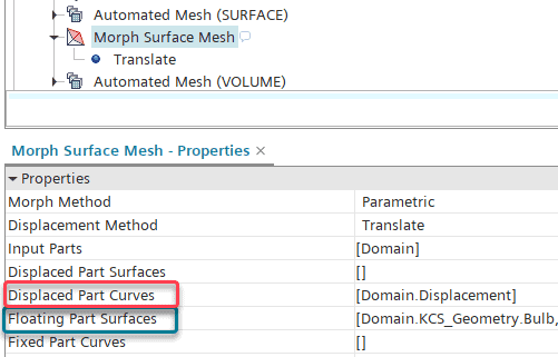
Real-World Applications for Hull Optimization
Many shipyards have physical models or existing vessels that represent proven designs, but lack digital CAD data. With parametric surface morphing, these hulls can be scanned and then used as the foundation for design exploration. The morphing parameters become optimization variables, allowing automated design studies to run efficiently.
The Author
Florian Vesting, PhD
Contact: support@volupe.com
+46 768 51 23 46