
In this week’s blog we will consider a cylinder, and more particularly how to mesh it in Simcenter STAR-CCM+. In the latest version, Simcenter STAR-CCM+ 2606, there was a cylindrical template-mesh made available for the trimmed cell mesher. There are many ways to mesh a cylinder or a shape that has a circular cross section. Here we will compare those and hopefully give an idea of when to use what method.
So, what ways do we have? There are slightly different methods for trimmer meshes and polyhedral meshes. Strictly, you can use the directed mesher with both a polygonal and quadrilateral source mesh, and while the polyhedral mesher has a cylindrical mesher template option, the trimmer mesher now has something similar. We will investigate the differences between these two options together with the directed mesh options.
Example case
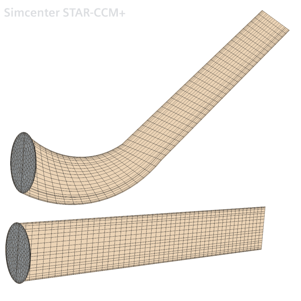
We will use the geometries below as a base for comparison between the different options. This represents the ideal cylinder on the bottom and a cylinder-ish shape that has a circular cross-section on the top. They will have different situations when different mesher types are preferable to use.
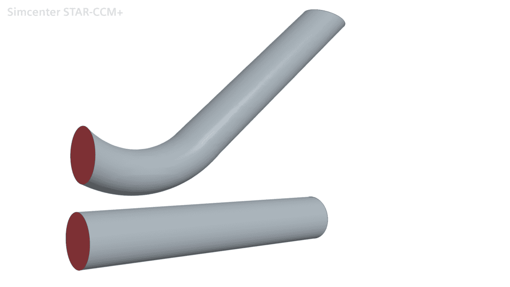
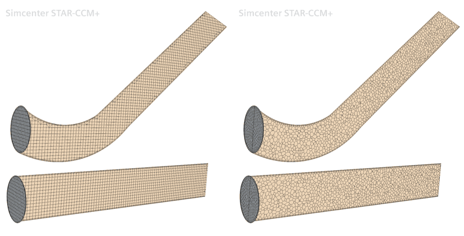
Base mesh types
To have a baseline we compare the results when using the base options for the trimmer and the polyhedral mesher, without any consideration that we have cylinders och cylinder-like shapes.
The polyhedral generalized cylinder mesher
This option is selected after the polyhedral mesher in the mesher selection. The result from it is very similar to certain settings for the directed mesher with polygonal surface base mesh. It does not provide any options for stretching of the mesh but uses some factor of the base size to determine the number of steps. It cannot be run in parallel. It also requires a clear distinction for the outer surface in terms of naming. It is no problem in a simple case like this but would not work at all if, for instance, two pipes would enter and exit a larger domain, unless the walls on the pipes are different boundary surfaces.
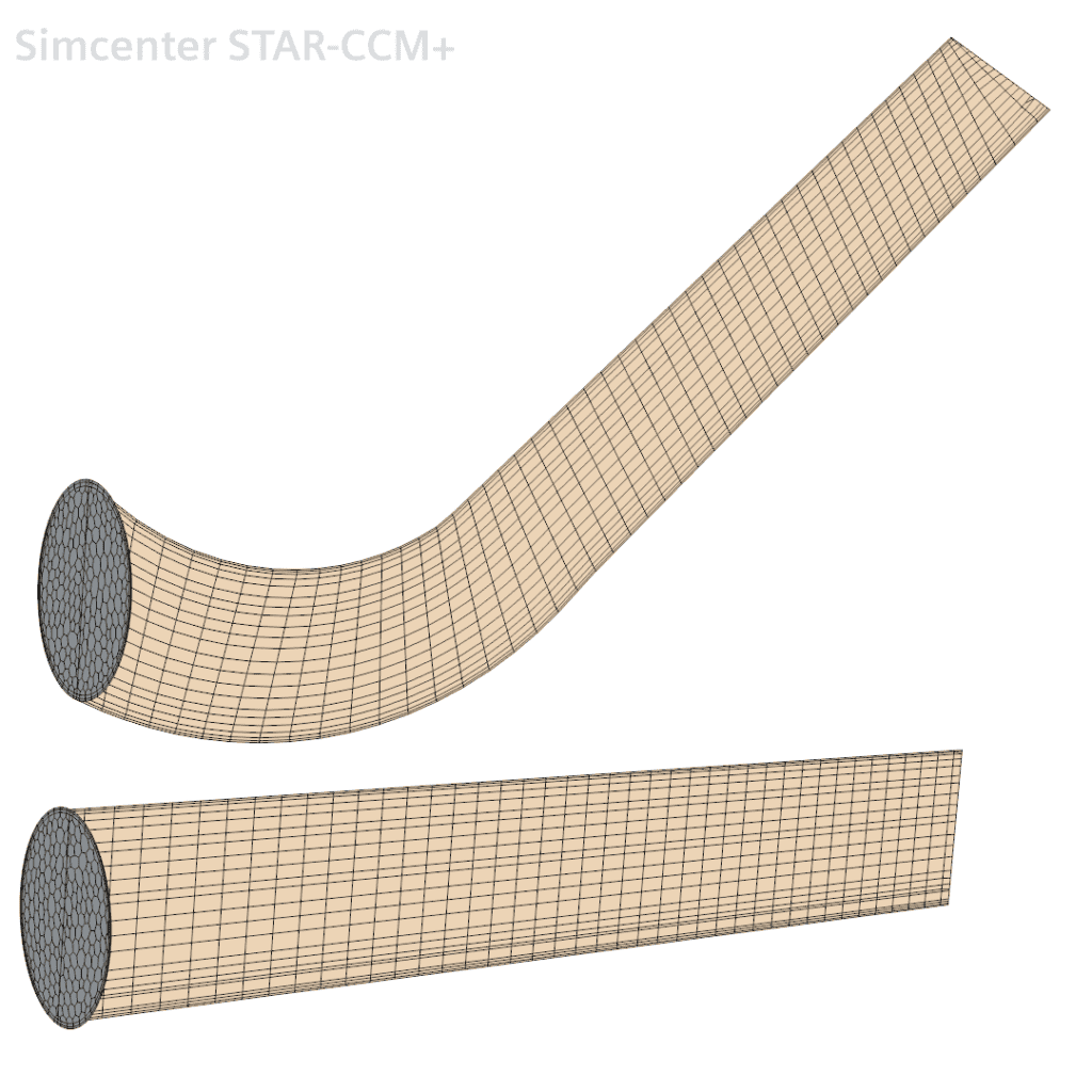
Directed mesher with quadrilateral mesh
The directed mesher can capture the geometric direction of the object you are sweeping your mesh through, hence likely also the flow direction. In the base form of the directed mesher, the source mesh created here on the inlet is meshed in a decent way to represent the circular appearance. You also have the option of deciding the number of steps from source mesh to target surface, together with the type of distribution. In the picture, the distribution is constant, but it can be geometric or hyperbolic as well.
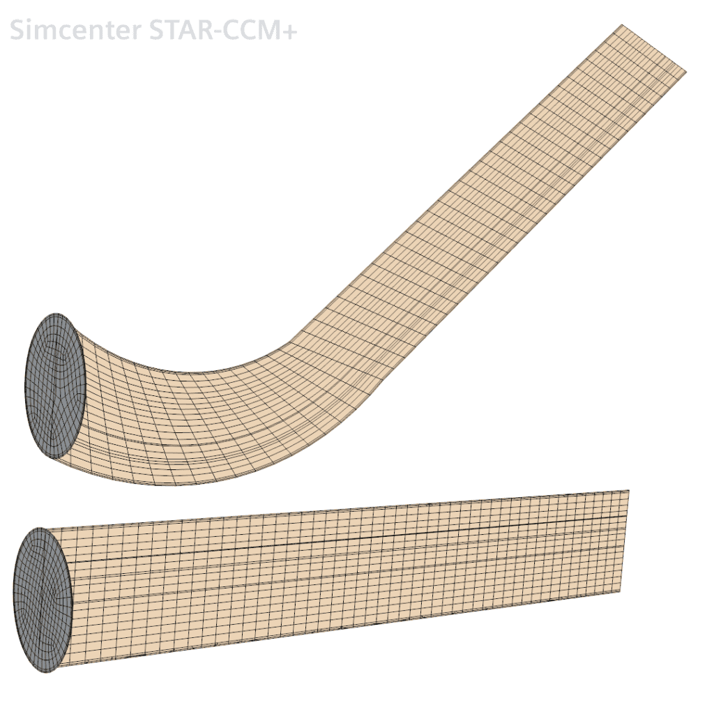
Directed mesher with polygonal mesh
There is no (or very little difference) in how the source mesh appears between the polygonal mesher and the polyhedral mesher, but as with the quadrilateral mesher, the polygonal directed mesher also nicely follows the curvature of the geometrical shape that is swept. With the same options as with the quadrilateral equivalent, you can alter the number of cells from start to end and the stretching type.
The new cylindrical template for the trimmer
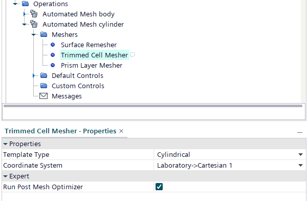
To utilize this new mesher option you need to select the template type “Cylindrical” and use either the Laboratory coordinate system (works here for the upper body since that was created first), or a self-created Cartesian coordinate system (a cylindrical will not work) to create base for the trimmed mesher.
It will result in the following meshes in these two different geometries. As you can see here the base mesh is still a trimmer mesh and any flow direction will not be followed for the curved geometry, but the result for the straight cylinder is good. The mesh will be created in the z-direction of the coordinate system you are using, whether the default coordinate system or one you have created yourself.
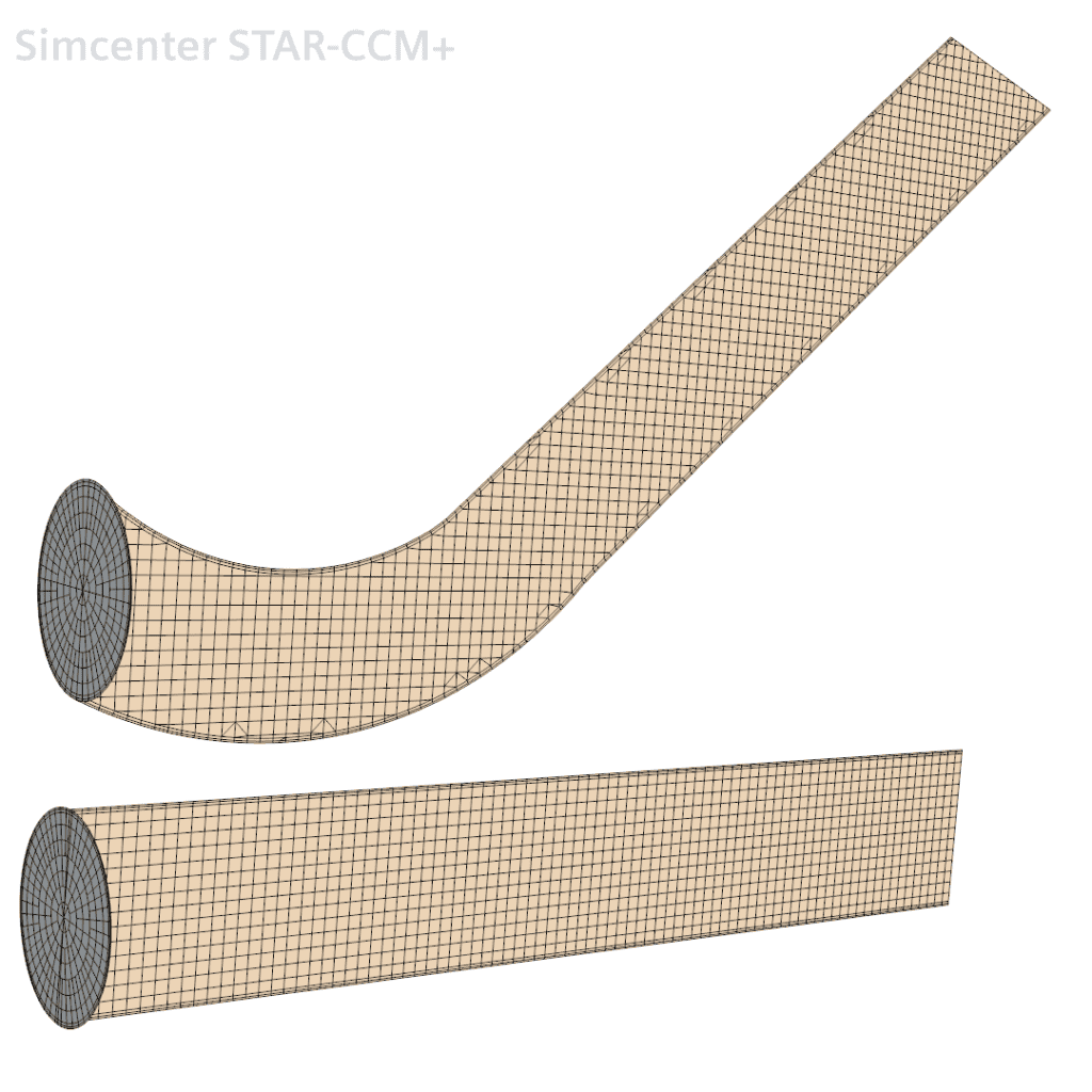
This is not the full truth for curved geometry. It looks here like an ordinary trimmer result, as if we used no special template. But the fact is here, that the mesh is created in 3 dimensions as if was a straight cylinder, meaning that the mesh will everywhere in the domain look like it is part of a straight cylinder, making its use a bit tricky for any other mesh than a straight pipe. It is possible to use on a geometry with variable radius, but it needs to be straight along the local z-coordinate.
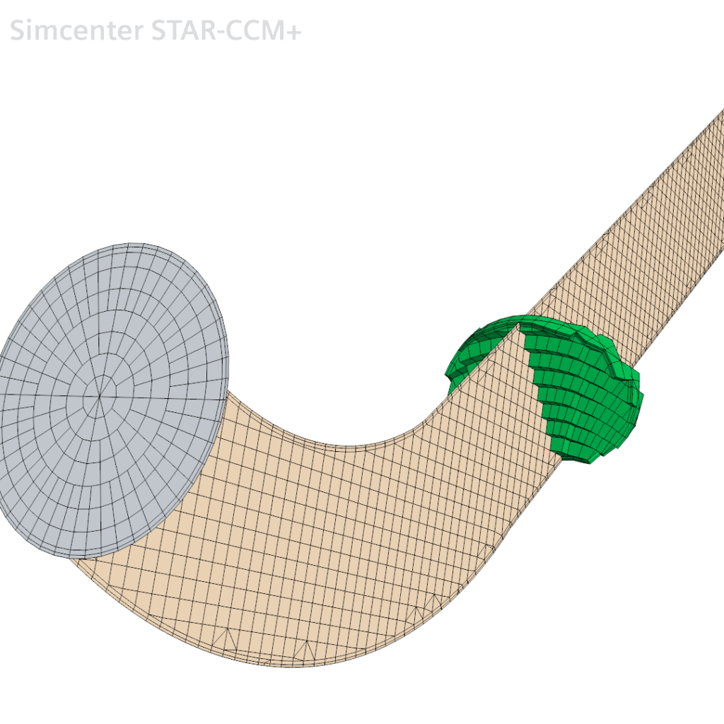
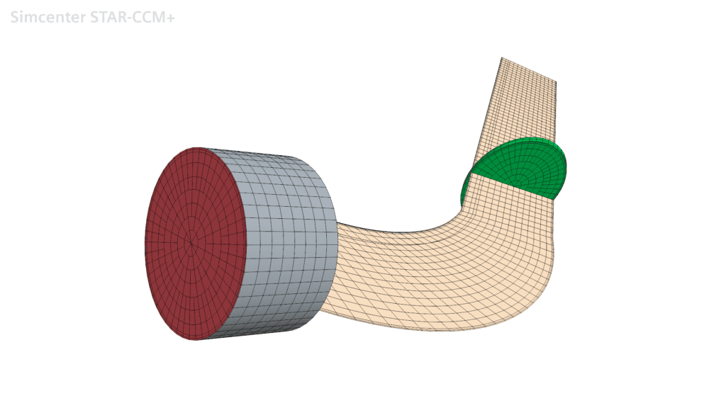
But what if we insist on using the result of the surface and try to force a sweep along our curved geometry, can we do that? Perhaps combining it with the directed mesher? One option would be to mesh it first with the cylindrical template to get the wanted surface mesh, then create a directed mesh and remesh the curved geometry while using the existing mesh. This unfortunately is not possible because of order in the operations. However, we have the option for the directed mesher when using a connected volume mesh. This means that we can create a small volume segment that is a cylinder and mesh prior to using the directed mesher. We mesh the small part with the new cylindrical template and use the connected mesh for source mesh on the long part with the directed mesh. This way we can use the new template and obtain the advantage of the surface mesh, with the directed mesher to capture the volume.
Summary
The directed mesher is still the best option if you wish to capture the curvature of a complex geometry, whether or not you combine it with the cylindrical template mesh, while the new cylindrical template for the trimmer mesher is good if you want a good source mesh in a straight pipe. The generalized cylinder option for the polyhedral mesher is a bit tricky to find good use for without comprehensive naming of boundaries.
Author

Robin Victor
support@volupe.com
