The bouncing ball paradox may be a sub-set of the golf ball paradox. The paradox is that if you try to bounce ball under a table it will exit from the same side that it was thrown from. It doesn’t feel that intuitive: at a first thought one would think that it would bounce in a zick-zack pattern, up and down and then exit on the other side!
Steve Mould explains it with very nicely in this video, You can’t bounce a ball under a table
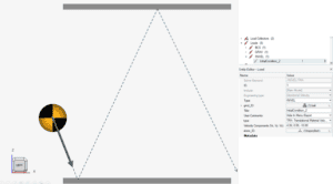
After I had watched this video, I thought it would be cool to simulate the same physics with Simcenter Radioss! In this blog we will investigate this phenomenon with an elastic ball bouncing between two rigid plates (floor and table). The ball will have an initial velocity of 10.8 m/s or 21.6 m/s (applied with the INIVEL/TRA card in Radioss).
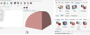
The ball itself is meshed with 4mm tet-mesh, starting with meshing 1/8th and mirror and merge at the common interfaces. The Simcenter Hypermesh to such commands are found under Topolgy/Mirror and under Validate/Equivalence.
The ball has a diameter of 5 centimeters with a soft elastic material applied to it with an elastic modulus of 20.8MPa. Distance between the rigid plates was set to 30cm.
There are some parameters that affect the outcome, like initial spin, contact friction, impact speed, E-modulus and mass. In this demo, contact friction and impact speed are varied. Initial spin is set to zero and angle of impact is constant.
The spin after 1st contact arises due to the inertia of the ball (moving mass along the line of action) and the frictional force resistance in the contact region. So, some of the linear momentum is transferred to a rotational spin and angular momentum.
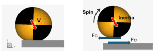
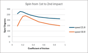
The same principle will apply for the remaining contact scenarios, but with lower speed and a spinning contribution at the contact interface. Gravity is included in the set-up, acting in -Z. Although the case is rather simple there are some physics involved which is interesting. If one measure the amount of spin, here expressed as angular rotation between 1st and 2nd impact vs the contact friction, it can be noticed that the amount of spin can have local maxima. When the ball hits the upper wall in the 2nd contact it will hit with back-spin and start to bounce outwards. The spin is presented for two different impact speeds of 10.8m/s and 21.6 m/s.
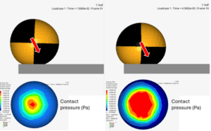
The maximum spin depends on the local contact condition as well as the amount of compression of the ball. This will affect the leverage of the center of intertia to the local point of contact at which spin occurs. When comparing the amount of compression for the two simulated impact velocities one can clearly see the difference in contact region and pressure distribution.
As indicated in the spin plot, there are conditions that are more favourable than others, animation shows the case when coefficient of friction is 0.15 and a impact speed of 21.6m/s
Hopefully you learnt something new regarding ball impact and got inspired to analyse interesting daily physics 😊!
Download and try out with your own settings:
As always, if you have questions about Simcenter Hypermesh, Simcenter Radioss or any other product in the Simcenter simulation portfolio, you can send us questions at support@volupe.com
Author

Johan Dahlberg
Contact: support@volupe.com