This week’s blog is dedicated to all you naval architects enjoying the latest release of Simcenter STAR-CCM+. In this last sequence of our season of news on Simceter STAR-CCM+, I summarize features which are interesting particular for you working with marine applications.Please check our previous posts for features like “Custom Tree” as initial tree view, “Scale-Resolving Hybrid (SRH) turbulence model” to to bridge the gap between URANS and DES and “Automatic Update” to create parts from Derived Parts together with the closed mode to automatically remove interfaces and zip edges.
 In automotive cases the new method showed improvements of the “Topology-Based” sliding mesh of in 1.3x faster simulations compared to the “the old way”. However, we typically have less propellers on a ship that wheels on a car. But self-propulsion tests with the Regal ship showed that the new method yields 3% faster simulations!


 A “Line of Action of Resultant force” can also be defined by the Force vector that was put on Center of Loads point. The Force vector will be showed in the console if you tick “Show Loads in Console” from Expert Center of Loads Properties. Also, the Center of Loads Report can be monitored, like all other reports.
 I hope these new features from the latest version of Simcenter STAR-CCM+ can be useful for your simulation tasks. As usual, do not hesitate to reach out with questions to support@volupe.com.Read also
How to transform Display views
Marine simulation with Simcenter STAR-CCM+
Release update on Simcenter STAR-CCM+ 2020.2 part 2
Templates and ini-files
I hope these new features from the latest version of Simcenter STAR-CCM+ can be useful for your simulation tasks. As usual, do not hesitate to reach out with questions to support@volupe.com.Read also
How to transform Display views
Marine simulation with Simcenter STAR-CCM+
Release update on Simcenter STAR-CCM+ 2020.2 part 2
Templates and ini-files
Enclosed angle
You might have encountered the need to measure the angle between two directions, which also might change in time. A maneuvering simulation with changing rudder angle can be an example simulation where this can be required. Now we have a report for that: Enclosed Angle Report. The new report allows to determine the angle between two direction vectors, each defined in a separate coordinate system which may be subject to motion. The report is available for all simulations with motion.How!?
In the report the two direction vectors are specified, between which the enclosed angle is to be computed. You select also the two coordinate systems the direction vectors are defined in. Since the angle between two direction vectors is always positive, an offset can also be specified to allow for signed angle measurements. The offset is added to the computed angle between the two direction vectors, giving the signed reported angle value.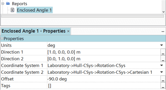
Faster sliding mesh interfaces
Ship simulation often require a ridged body motion to capture transient and unsteady flow phenomena, like a propeller simulation. These employs sliding mesh interfaces whose interface intersection is performed at every time step. A portion of that update is calculated in serial and is the bottleneck when scaling parallelization on many cores (>512 cores).A new “Topology-based interface” method has been introduced that uses a fundamentally threaded approach to perform the intersection. It renders much faster and is better scalable than the current “Geometry-based interface” by taking advantage of shared memory parallelization.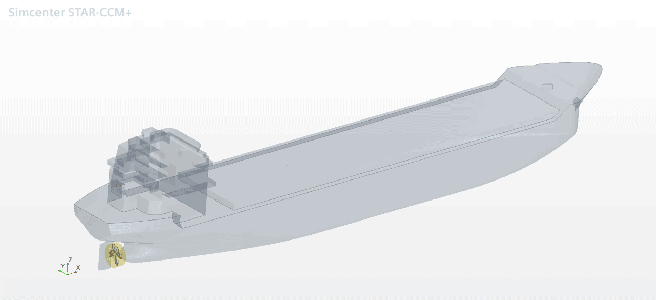 In automotive cases the new method showed improvements of the “Topology-Based” sliding mesh of in 1.3x faster simulations compared to the “the old way”. However, we typically have less propellers on a ship that wheels on a car. But self-propulsion tests with the Regal ship showed that the new method yields 3% faster simulations!
How!?
You may note that there are two options available for interface properties. The old legacy option is renamed “Geometry-Based” and the new option is named “Topology-Based”.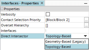
Volume of Fluid (VOF) wave damping/forcing by boundary
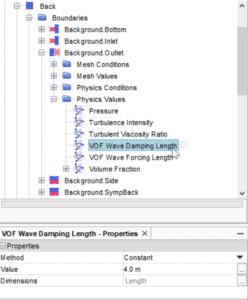
The computational cost of marine simulations is brought down significantly by allowing wave damping and wave forcing to be used together now in the new version 2020.3. Both options were available previously, but they were mutually exclusive available by programming field functions to be used in Momentum Source Option. Allowing these options together allows the computational domain to be kept small even on wave simulation when enforcing incoming wave shapes. Wave damping is used at outlets to suppress outgoing waves before they have a chance to reflect from the outlet. This allows the computational domain to be kept smaller than it would otherwise be. Wave forcing is used at inlets to enforce the desired wave shapes over a volumetric region. Now it is possible for you to specify both forcing and damping together in the same simulation on a per-boundary-basis.How?!
The set up is now easily done from the GUI interface by soecifying “Combined Forcing and Damped”, providing specific length for each method and selecting or even combining the methods per boundary.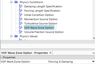
Flexible DFBI
You can now take the deformation of your floating structure into account and simulate the Fluid-Structure Interaction more efficiently than ever before. This is made possible through a hybrid approach. A 6DOF model is used to solve for the rigid body motion, while a continuum Finite Element model is used to compute the deformations. The separation of rigid body motion and deformation makes it possible to maintain the linearity of the FE model. This is much more efficient than a regular FSI approach where the rigid body motion and the deformation is being solved on a none-linear FE continuum model. 3 options are available:- DFBI- Deformable body allows you to model your entire body as flexible. For example, you may wish to model the deformation of your boat frame and hull.
- DFBI – Partially deformable body can be used to model some parts of your structure as flexible and others as rigid. For example, you may wish to model the boat frame as rigid, and only the hull as deformable.
- DFBI – Deformable moving attachment allows you to model a rotating propeller attached to the boat. The deformations of the propeller will be considered. This functionality has been released previously.
How?!
Adaptive Mesh Refinement (AMR) updates
Sometimes you need simulations to establish flow features before you can turn on AMR. Now you can utilize the powerful “Update Events” framework and incorporate logical triggers and create a combination of triggers, for example to trigger AMR only after the flow has developed.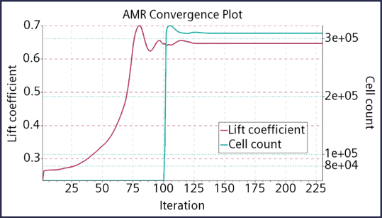
How?!
In the example above AMR is triggered only after 100 iterations and we can spare unnecessary adoption during high fluctuations of flow characteristics.Center of Loads Report
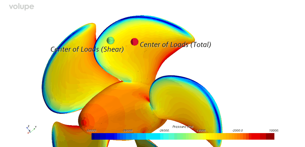
A new Report is available to give you the location where the forces of fluid flow act on your input parts. Center of Loads report has several customization controls:- can consider pressure forces, shear forces, or both
- can be located on Part Geometry surface or Reference Plane

How?!
To create a Center of Loads Report, right-click the Reports folder in the sim tree, then select “New Report -> Flow / Energy -> Center of Loads”.In the output console, in addition to Center of Load coordinates of individual parts- one can also specify whether to show the Force and residual Moment in the report’s console output.
- Force and Moment Units can be specified as well if Show Loads in Console is checked
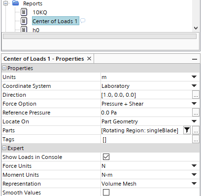 A “Line of Action of Resultant force” can also be defined by the Force vector that was put on Center of Loads point. The Force vector will be showed in the console if you tick “Show Loads in Console” from Expert Center of Loads Properties. Also, the Center of Loads Report can be monitored, like all other reports.
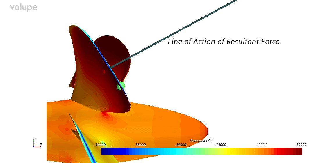 I hope these new features from the latest version of Simcenter STAR-CCM+ can be useful for your simulation tasks. As usual, do not hesitate to reach out with questions to support@volupe.com.Read also
How to transform Display views
Marine simulation with Simcenter STAR-CCM+
Release update on Simcenter STAR-CCM+ 2020.2 part 2
Templates and ini-files
I hope these new features from the latest version of Simcenter STAR-CCM+ can be useful for your simulation tasks. As usual, do not hesitate to reach out with questions to support@volupe.com.Read also
How to transform Display views
Marine simulation with Simcenter STAR-CCM+
Release update on Simcenter STAR-CCM+ 2020.2 part 2
Templates and ini-files