While working with geometry handling in Simcenter STAR-CCM+ you have probably come across the concepts of Tessellation, CAD Projection and CAD Boolean, but perhaps the meaning of them all is not entirely clear. In this week’s blog post we will explain these features in more depth and how they are tied together.
Geometry
Typically, a virtual representation of any geometry (in engineering at least) is made with CAD. A CAD tool describes a geometry with mathematical and geometrical formulations, meaning it can be presented with different levels of resolution. When performing a CFD simulation in Simcenter STAR-CCM+, or any other CFD software, we approximate these geometrical features by discretizing into a computational mesh with a fixed (or finite if you will) number of discrete points in space. Now, the baseline for such a mesh in Simcenter STAR-CCM+, is always going to be a tessellated representation of the CAD geometry. So, what is tessellation?
Tessellation
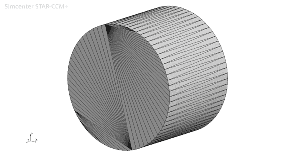
Tessellation can be seen as a surface mesh approximation of the CAD geometry, built up by a collection of triangular elements (often similar to STL format). As such, it is a geometry representation with a fixed resolution that has no mathematical description of the curvature. Below you see an example of a tessellated cylinder.
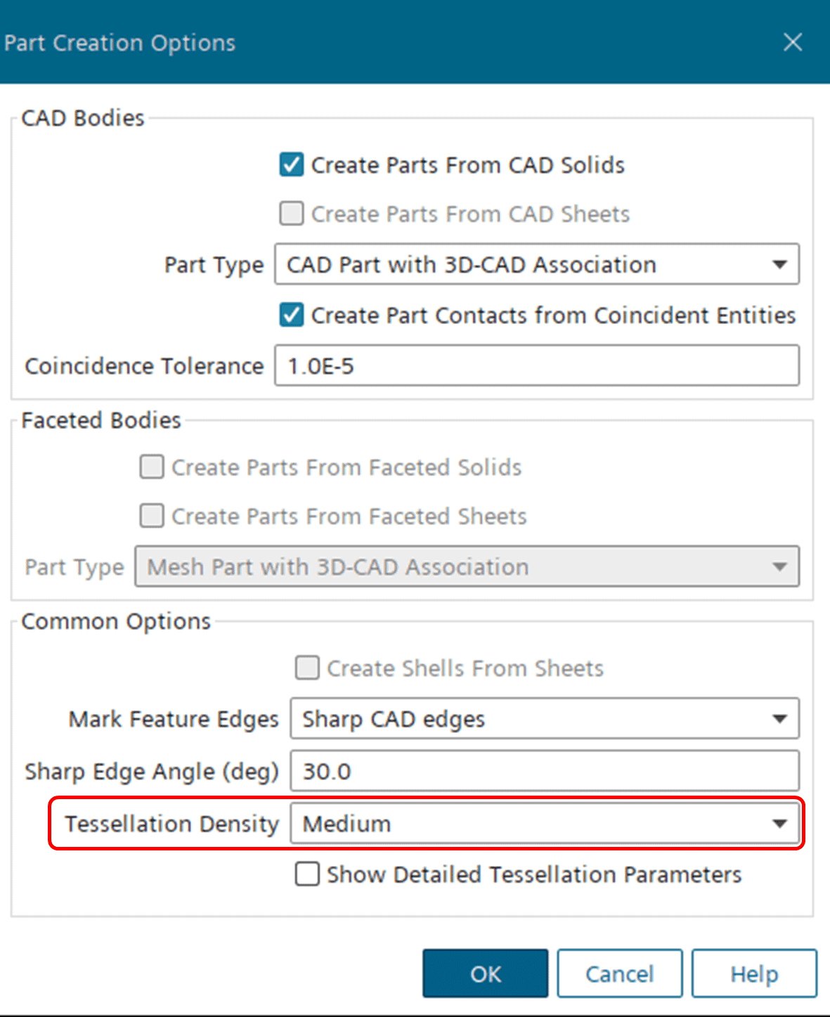
Generally speaking, this means that the tessellation density (i.e. the discretization resolution of the surface curvature) dictates the maximum resolution of the surface mesh curvature. In Simcenter STAR-CCM+, you choose this level of resolution when importing a geometry into the simulation by selecting the Tessellation Density (see picture below).
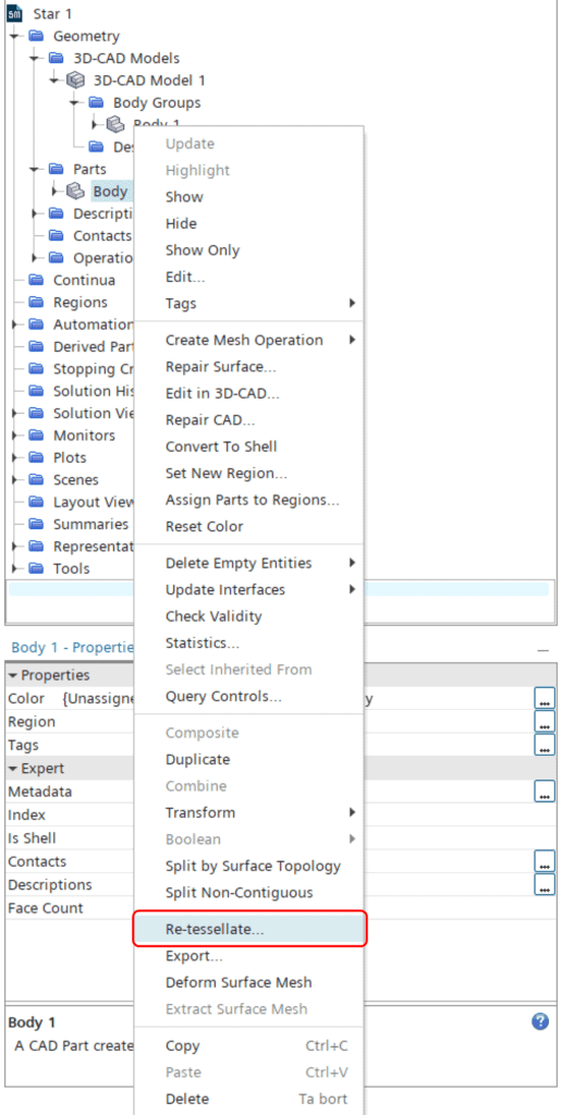
It can be interesting to know that as long as you are importing CAD geometry, you can always re-tessellate your parts at a later stage. For very big models it may therefore be a good choice to stick with a relatively coarse tessellation at import (default is always “Medium”), in order to not spend a lot of time tessellating the whole geometry with very small elements during import. To re-tessellate a part, you simply right-click the part and select “Re-tessellate…” (see picture below). This action will prompt you with the Tessellation Density options that you see during geometry import.
As mentioned above, the tessellation will always be the foundation for the surface mesh, meaning that the surface mesh cannot be finer (in terms of curvature) than the tessellation it is based upon. However, as is often the case, there is an exception to the rule.
CAD Projection
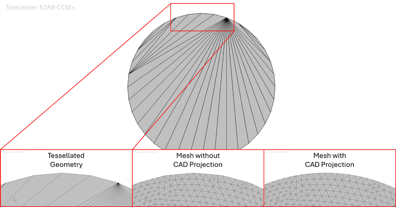
In cases where you have imported your geometry in CAD format, you will have an inherent connection between the tessellated part(s) and the CAD part(s). Under such circumstances, the tessellation density is not necessarily the limiting factor for the surface mesh curvature resolution. This is thanks to a feature called CAD Projection, which is included in the Surface Remesher (and the Surface Wrapper). When CAD Projection is active and there is a connection between the tessellated part(s) and the CAD part(s), the Surface Remesher (or Wrapper) will project vertices of the surface mesh back onto the CAD formulated surfaces to better resemble the original geometry. Below is an example of a cylinder with a coarse tessellation, meshed both with and without CAD Projection. If you look closely, you will see how the mesh with CAD Projection has a more continuous curvature (similar to the CAD), while the mesh without projection has the exact same curvature resolution as the tessellated geometry.
So, does this mean that tessellation density doesn’t matter if we use CAD Projection? No, it still does. But CAD Projection can help to vastly improve a coarse tessellation. A higher tessellation density will always create an even better stencil for the CAD Projection, but as always, accuracy comes at a cost. Hence, an inexpensive tessellation density combined with CAD Projection is often a viable option.
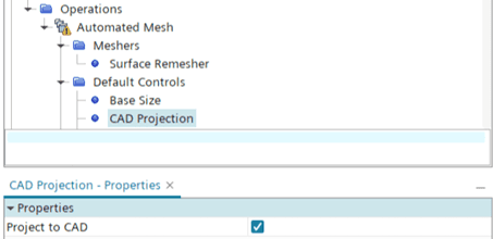
CAD Projection is always activated by default, so if you don’t want to use it you need to deselect it in the Default Controls. It can be interesting to know that according to the user guide, projecting vertices to CAD increases the time required for the Surface Remesher by up to 300% (or more). For this reason, it could be worth deselecting CAD Projection if you know you have a very good tessellation already. For the Surface Wrapper the increase is only about 20% though.
CAD Boolean
When performing Boolean operations on imported (i.e. tessellated) parts inside the simulation environment (i.e. outside 3D-CAD), you may have noticed that you have the option of performing a so-called CAD Boolean (the picture below shows an example).
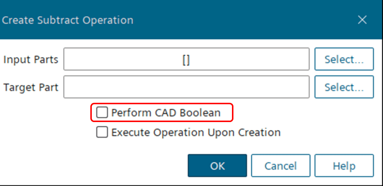
By default, all Boolean operations inside the simulation framework are performed on tessellated geometries, meaning that any upstream pre-processing or manipulation (e.g. surface repair) will end up in the resulting part. This is usually referred to as a Discrete Boolean, since it is performed on a discrete surface mesh representation, and the resolution of the output part will be directly related to the tessellation resolution of the input parts. Now, if all the input parts in the operation are CAD bodies, it is possible to perform a CAD Boolean instead. This option means that the operation utilizes the original geometry formulation as input, hence disregarding any upstream tessellation. The output part of such an operation will be a CAD body and will instead be re-tessellated based on the new geometry. Activating this option therefore gives the possibility to adjust the tessellation density of the output part (see example below).

If you want to know more about these topics you can find more detailed information in the Simcenter STAR-CCM+ User Guide. And as always you are welcome to send in any questions to support@volupe.com.
Author

Johan Bernander, M.Sc.
Application Specialist