One of the highlights from this year’s releases of Simcenter STAR-CCM+ surely must be the Virtual Body motion, which first saw the light of day in version 2502. Fast forward to the release of version 2510, and this new motion feature was improved even further by making it compatible with Dynamic Fluid-Body Interaction (DFBI). This week’s blog post will present an example of this combination in use – and to top it off we’ll also present a workaround for including prism layers on the Virtual Body.
Huey, Dewey or Louie?
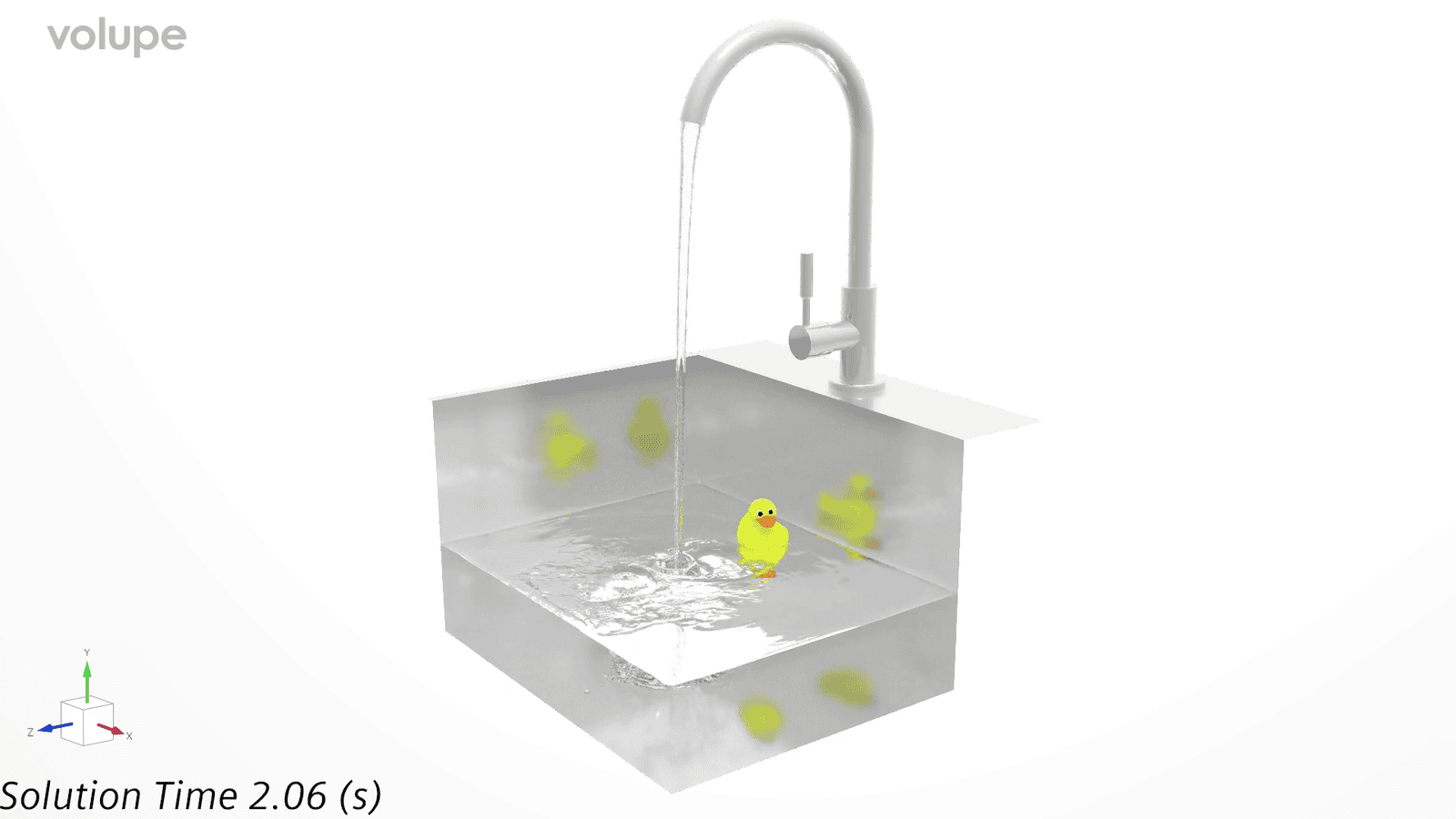
No, this is not an episode of Duck Tales. But to demonstrate the feature of Virtual Body with DFBI we will reunite with our rubber duck friend who you may have seen in some previous articles. In this example we will let him take a swim in a kitchen sink, while also pouring in some additional water from the faucet.
The setup involves a VOF multiphase model with water and air, a Virtual Body boundary (the rubber duck) and a DFBI Virtual Body motion (which is the name of the newly introduced feature). To minimize computational workload, we also include Adaptive Mesh Refinement (AMR), both for the free-surface and the Virtual Body.
The Virtual Body setup
The concept of Virtual Body motion has some similarities to the overset mesh approach, where you build a so-called background mesh and then allow for an object to move within the domain. The key difference is that with the overset technique, the static and moving parts are interfaced and overlapping, while the Virtual Body technique relies on continuously subtracting the moving object from the background mesh, while also detaching and reattaching mesh vertices onto the created void (i.e. virtual body) as it moves. Below is a video from the simulation where you can see the cut-out of the duck (i.e. the Virtual Body boundary) and the mesh refinements around the duck and the free surface.
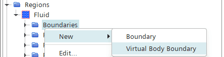
One of the biggest upsides of the Virtual Body motion certainly must be its simplicity and ease of use. The workflow is so simple it can often be setup in a matter of minutes – you simply mesh the background domain and then add the moving part(s) as a Virtual Body boundary. No need for interfaces, and the subtraction is done on the go by the algorithm. The Virtual Body boundary is created by right-clicking the Boundaries folder of the Background region, as shown below.
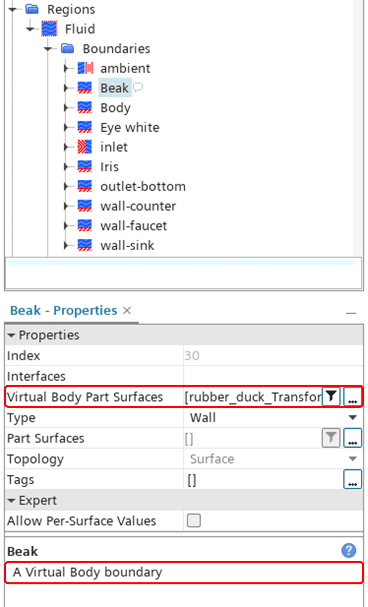
Once created, you simply assign the moving parts to the Virtual Body boundary. In this specific example I created four separate Virtual Body boundaries for post-processing reasons (the body, the beak, the irises and the eye whites), but function wise they could all have been put into only one. The properties for the boundary will then indicate that it is a Virtual Body boundary, as shown below.
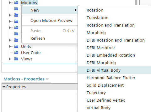
The DFBI Virtual Body motion is created under Tools -> Motions just as any other motion, see below.
The motion is then assigned to the Region’s Physical Values folder, again just as it would for any other motion.
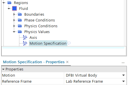
The distinct difference between a DFBI Virtual Body motion and a prescribed motion is that the DFBI motion is enforced by the forces exerted on the body (e.g. fluid and gravitational forces). To account for these forces we need to setup a 6-DOF Body from the DFBI folder, as seen below. The DFBI folder appears in the simulation tree when you assign a DFBI-type motion to a region.
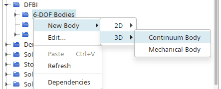
Then you go ahead and assign relevant properties such as degrees of freedom (DOF), body mass, center of mass, moment of inertia etc.
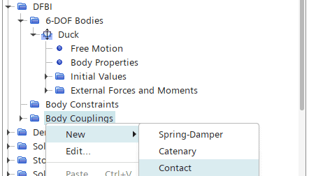
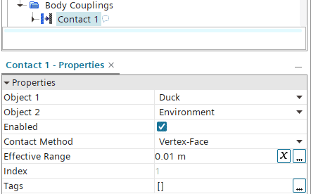
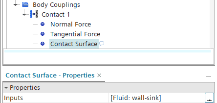
In this case we want the duck to be constrained within the sink, so we also need to setup a Contact Body Coupling between the duck and the sink wall. We create the Contact from the Body Couplings folder, then set the objects as Duck and Environment and finally select the sink wall as the Contact Surface. Typically, you need to pay attention to the contact forces as well, but that lies beyond the scope for this example.
Now we are done with the DFBI Virtual Body motion setup, but to induce some additional turbulence and wavy motion in the sink we also add some incoming flow from the faucet. Now we are ready to run the simulation. The final result can be seen below.
What the duck, no prism layers!?
As you may have spotted in the first example, there were no prism layers on the Virtual Body. And as a matter of fact, one obvious drawback with the Virtual Body is that it is not possible to include prism layers on the moving boundary (at least not yet). There is however a workaround solution to get it done. The idea sort of builds on the overset mesh approach, where the moving body has a surrounding mesh that moves along with the body, with the moving mesh being interfaced to the background domain. This way you can let the moving body have prism layers, while offsetting the Virtual Body boundary away from the actual DFBI body. Let’s demonstrate this approach with the floating duck.
How to include prism layers on the Virtual Body
The picture below shows a snapshot of the conceptual setup in a case like this. In this setup, the pinkish box is treated as the Virtual Body (rather than the duck), and moreover it is treated as a separate region which is also interfaced with the background region.
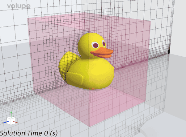
In this setup, the duck itself must be subtracted from the virtual body box upfront, giving the final moving object (i.e. the pinkish box with a void for the duck). The beauty, however, is that the duck boundaries can still be used as input to the DFBI motion.
To summarize, the steps to take are
- Mesh the background region.
- Create the Virtual Body part by subtracting the moving object (i.e. the duck) from a surrounding box.
- Assign the Virtual Body part to a separate region.
- Create a Virtual Body boundary in the Background region and assign the Virtual Body part surfaces to it.
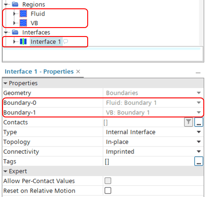
- Interface the Virtual Body boundary in the Background region with the corresponding boundary in the Virtual Body region.
You should end up with two regions, the background and the Virtual Body (“Fluid” and “VB” in the picture below, and an interface between the two.
Now to the motion part of the setup. In the previous example, all parts belonged to one single region. In that case we had to use the DFBI Virtual Body motion, which combines a DFBI motion with a Virtual Body motion – all in one. In this example however, the stationary parts and the moving parts are put in separate regions, meaning the motions must be treated separately as well. This means that we need to create two new motions:
- A Virtual Body motion (for the background region), and
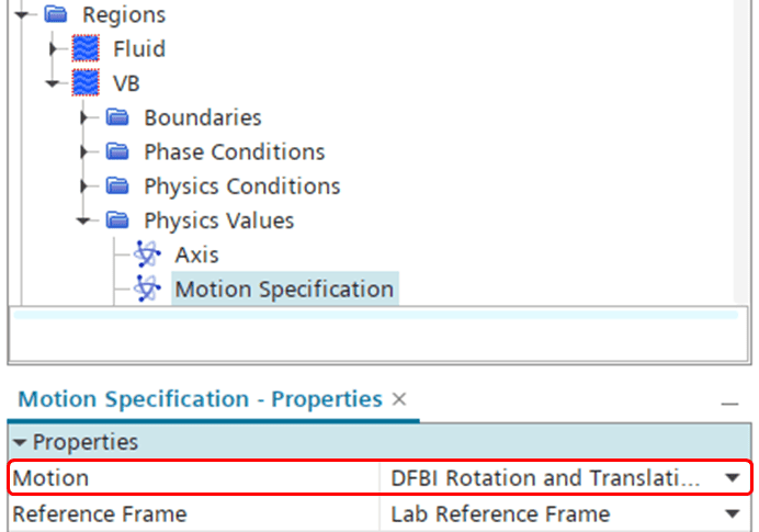
- A DFBI Rotation and Translation motion (for the moving region).
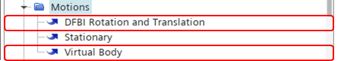
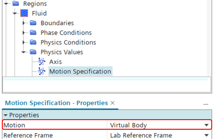
As indicated above, we assign the Virtual Body motion to the Fluid (i.e. background) region, and the DFBI Rotation and Translation to the VB (i.e. moving) region.
Lastly, you setup the 6-DOF body in the DFBI folder, along with the needed Body Coupling. The 6-DOF body setup can be done just as in the first example, and as mentioned above, the duck boundaries in the VB region can be used as input to the DFBI body similar to before. The final result is a duck meshed with prism layers moving as a DFBI body. The result can be seen in the video below.
I hope this demonstration will be helpful for showing how you can work with Virtual Body motions. More details on Virtual Body can be found in the User Guide, or in this blog post where we introduced Virtual Body back in March this year:
New CAD And Mesh Features In Simcenter STAR-CCM+ 2502 – Volupe.com
As always, you are welcome to send in comments or questions to support@volupe.com.
Author

Johan Bernander, M.Sc.