Nowadays, we as users of Simcenter Amesim are accustomed to being able to freely pick and choose from a very large set of pre-defined physics-based components covering most applications and potential areas of interest. This has allowed us as engineers to wholeheartedly focus on the problem of analyzing our system and assess behavior by for example subjecting it to various harsh scenarios using simulation. All this while being assured that the underlying physics is fully described and correctly captured by the tool.
Now, in situations where a pre-built component does not entirely match your requirements, new components can be created by connecting different primitive components, or “building-blocks”, together to form new equipment. This is where the Component Design Libraries in Simcenter Amesim come in. Component Design is available for pneumatic, hydraulic and multiphase flow, covering the different fluid regimes and allowing for custom, and parameterizable, models to be created without the need of writing a single line of code.
In this article we have a closer look at the approach for creating detailed component models and familiarize ourselves with the necessary steps by considering a more complex model of a variable displacement vane pump. To provide a few other examples of what is possible using these libraries; different types of detailed pumps and compressors, such as Gear pumps, Variable Axial Piston pumps, pneumatic compressors. Novel designs for solenoid valves, injectors, pressure regulators, components present in active suspension systems, to name a few.
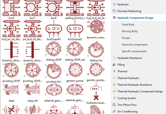
Image showing parts of the Hydraulic Component Design library containing primitive components for modelling diaphragms, leakages, sealings, pistons, pumps and poppets.
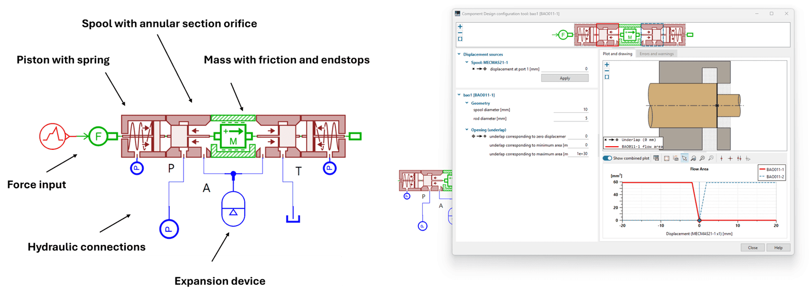
Below a rather simple example of a custom 2-way valve is given. This component model was created using several primitive components from the Mechanical, Hydraulic and Component Design library.
In the illustration below the valve’s different parts are named. Along with the ability to use “building blocks” to produce assemblies, a tool is provided to visualize geometrical changes and the final geometry of the elements making up your part.
We proceed by considering a more detailed and complex component model of a rotary vane pump. Vane pumps are a common means of fluid transport and pressure increase and used in several applications, such as in lubrication systems, vacuum applications, fuel pumps.
A vane pump consists of a pump housing, an off-center rotor, sliding vanes which are slotted along the rotor, a stator ring and a drive shaft. As the rotor turns, the vanes follow the rotating motion and slide along the stator ring’s inner wall. Thereby following the profile of the stator to form expanding and contracting chambers that draw fluid in through the inlet and discharge through the outlet. Vane pumps may also be configured so that the eccentricity of the rotor in relation to the stator ring can be varied during operation. By pivoting the stator ring about a fixed axis, the pump’s volumetric flow rate can be regulated through variation of its effective displacement.
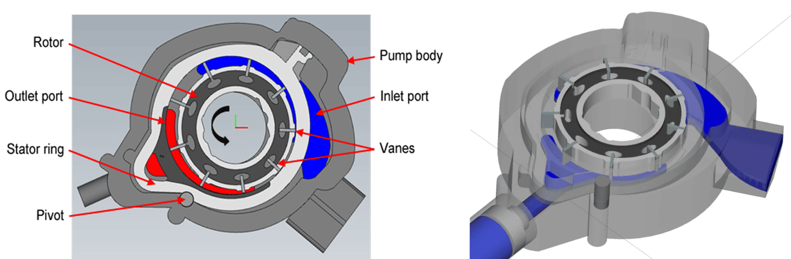
Figure illustrating the main components of a rotary vane pump. Note that the vanes, which are slotted into the rotor, are not radially fixed. Instead, they are free to move inward and outward, allowing them to slide along the inner surface of the stator ring.
Creating a more detailed model of the rotary vane pump, rather than selecting a pre-built library component, serves several purposes. By introducing more detailed geometric specifications and behavioral characteristics into the model, modifications to parameters such as vane clearance, rotor diameter, stator ring grooves, flow passage areas, internal leakage paths, and rotor eccentricity can be systematically analyzed and assessed. This enables precise control of the pump’s displacement and helps ensure stable pump operation.
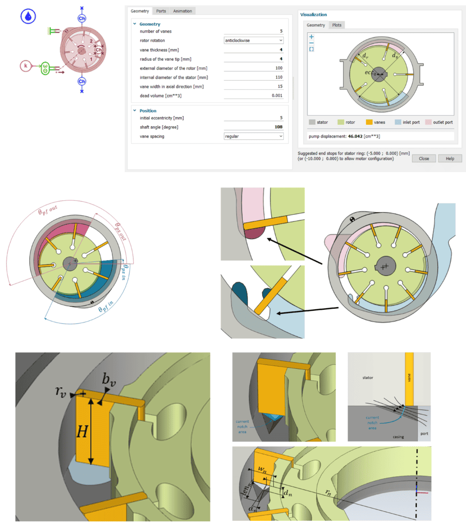
In addition to modeling the main parts within the pump housing in greater detail, the following parts should be added to more accurately capture the pump’s dynamic behavior during operation: a mechanical pivoting mechanism for the stator ring (capable of managing the compression and expansion of the fluid within the vane chambers which generate forces acting on the cam ring), a solenoid-actuated spool valve to regulate the pivot motion and thereby control the delivered flow rate, and representations of internal and external leakage flows arising from clearances and tolerances.
The complete component model is presented below, together with images highlighting the function of the main parts.
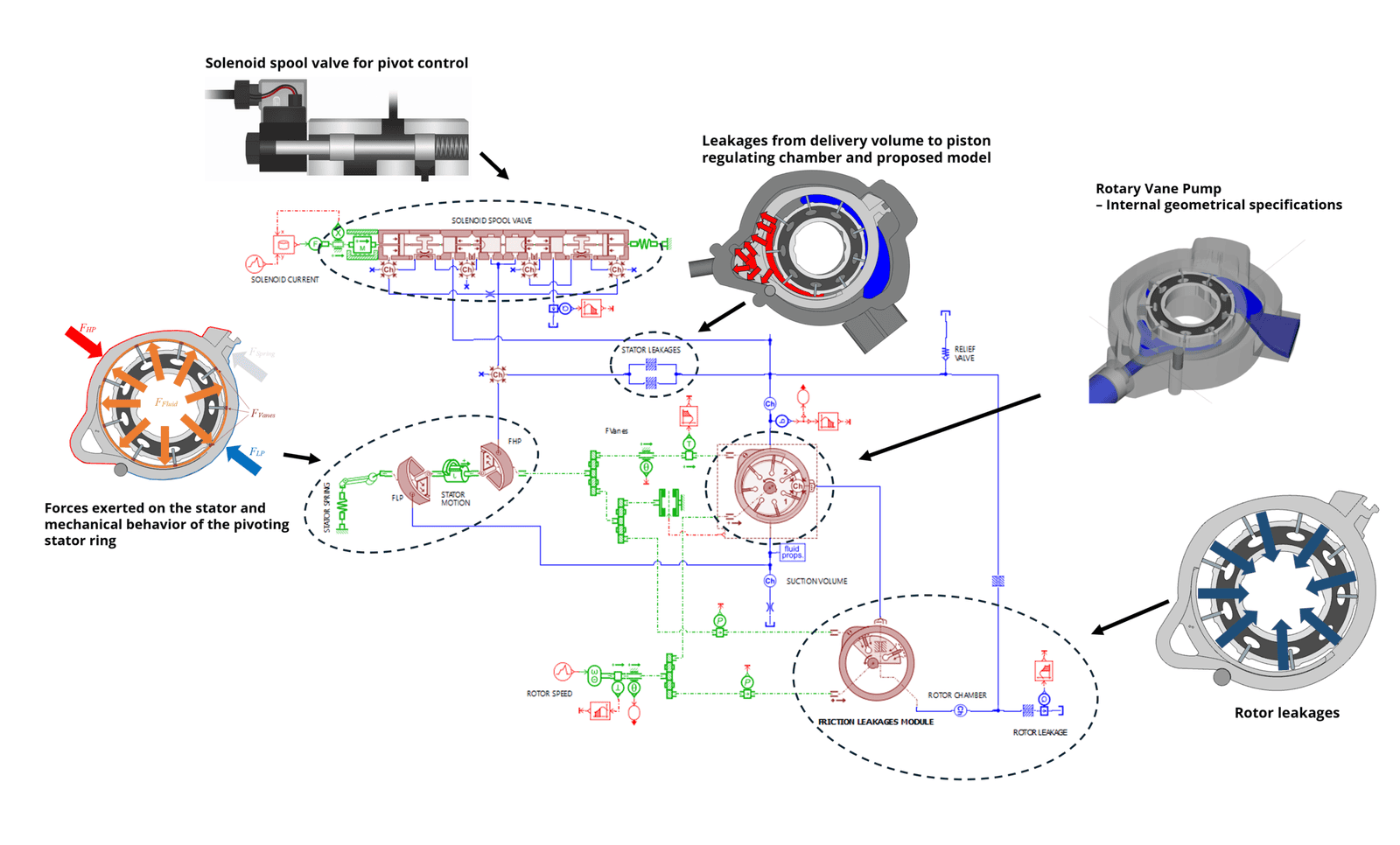
With these additional behavioral modifications, the pump’s dynamics and performance when shifting stator position can by studied, as a more thorough representation of the pivot mechanism and exerted forces are included in the model. The inner workings of the solenoid valve are modeled in detail, enabling extensive parameterization and optimization studies to identify the most suitable valve configuration for the vane pump. Flow leakages are more appropriately described granting the possibility to study how geometric changes and pump control may decrease unwanted losses to discharge pressure. Moreover, design studies may be performed to evaluate several different pump shapes, e.g. number of vanes, dimensions of the stator and rotor, outlet and inlet shapes, grooves, and notches.
The model allows for rapid simulation and is capable of producing angle-resolved or cycle average results for a number of key parameters such as, instantaneous discharge pressure and flow rates, the individual and overall torque required, creation of pump characteristics curves, w.r.t. rotational speed, volumetric flow rate and pressure rise, from cycle averaged results, monitoring changes to the eccentricity of the stator ring as the solenoid valve actuates the pivot control.
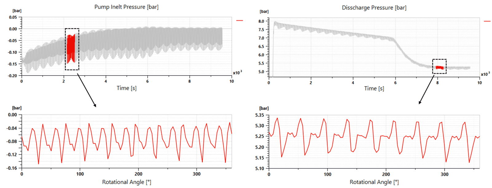
Suction and discharge pressure w.r.t. time [s] and rotational angle [°]. Note that the delivered pressure is modulated by the pivoting motion of the stator ring during the simulation.
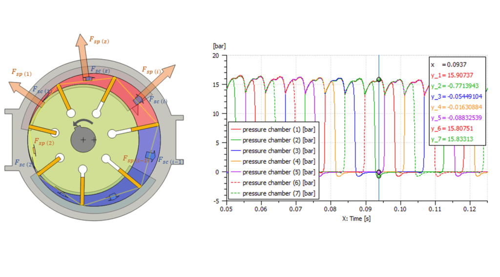
The evolution of the forces and pressures within the pump’s indevitual volumes may also be monitored throughout a specific cycle. In the figure below, the pump’s chambers are highlighted, along with the pressure evolution for the seven different chambers. Appropriate balancing of the drive shaft due to these varying internal forces becomes important.
We hope you have found this article interesting and learned more about how to create detailed component models in Simcenter Amesim, as well as, different types of analysis possible using such an approach. If you have any questions or comments, please feel free to reach out to us at support@volupe.com.
Author
Fabian Hasselby, M.sc.