The visualization tools in Simcenter STAR-CCM+ are integrated with the analysis, allowing for the interactive extraction and viewing of solution data from either a running or converged simulation. This makes it possible for you to watch a flow field evolve as the simulation iterates and immediately see the effects of those changes. But how to save the intermediate steps to for instance of a transient simulation? Well, Simcenter STAR-CCM+ allows you to both export your scenes at runtime or to save selected data in a Simulation History file.
Let´s start with the most straight forwards approach:
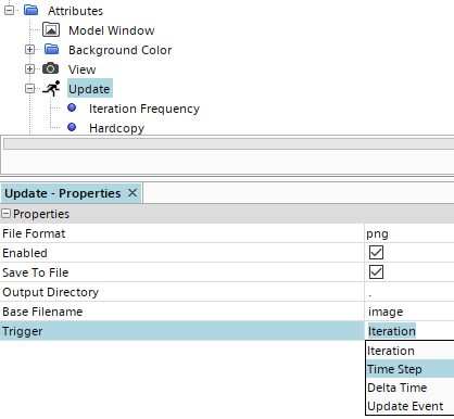
Save a Hardcopy of your scene
Saving you scene to a file can be trigged by different events like Time Step, Iteration or Delta Time. Eventually, you can combine the images to an animation file. But this means that you only have the scene (it can even be a scene file) saved, no additional data.
Simulation History
In case you are interested in details of the flow analysis, Simcenter STAR-CCM+ provides the simulation history file (.simh) to which you can save selected data while a simulation is running. After the simulation completes, you can load this file and query its states for post-processing.
Stationary view
In some cases, it can be useful to transform a displayer of transient data to keep the geometry stationary. Let´s say you have a rotating geometry in the flow and you are interested in how the pressure distribution changes in time. It would be most comfortable to look at on object that is not rotating.
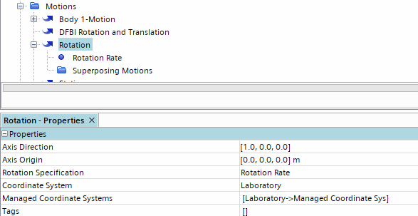
To do so, you create a coordinate system and let the motion (Rotation in this case) control the coordinate system.
- Create a new coordinate system “Managed Coordinate Sys”
- Manage the coordinate system by your Motion
3. Set the view of your scene to the managed coordinate system.
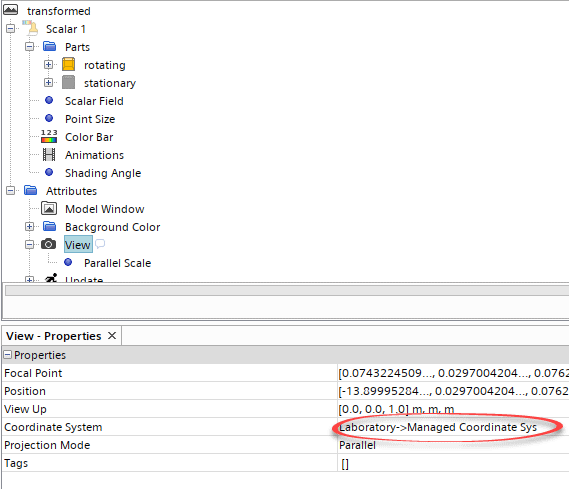
However, coming back to our Simulation History, the managed Coordinate system is relative to the sim file and a solution view doesn’t store its own coordinate system. The information to transform the view is thereby lost in translation when saving the intermediate result to a Simulation History.
But there are two possible workarounds to store the information of your rotation motion. In both cases we use a report to store the information of the rotation angle with the other field information in a simh file.
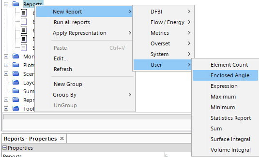
Option 1: Enclosed Angle report
The Enclosed Angle Report (new feature in version 2020.3) outputs the angle between two direction vectors, each defined in a separate coordinate system which may be subject to motion. In our case, we can measure the angle between the Laboratory Coordinate System and the Managed Coordinate system (setup as described above).
Before runtime:
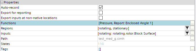
1. We define a report and include that report in the Simulation History
2. After the case run, go to Solution Histories, right click and Create Recorded Solution View
3. Create a report of some kind, for example a Surface Average Report, and rename it with something meaningful (rotationHistory in this example)
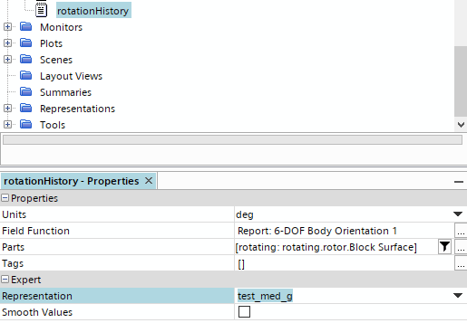
4. Edit the report selecting as Field Function Report: Enclosed Angle 1, a part that is present in the solution history, and change the representation to the recorded solution view you have created from the solution history at hand
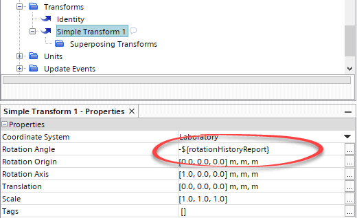
Now, we need Graphics Transforms (Tools > Transforms) to modify the default position of the part in the displayer. By default each simulation contains one transform named Identity. You can create additional transforms, like Simple Transform which can be a translation, rotation and scaling. Using a Simple Transfrom can simply move the geometry back to its original position in the scene.
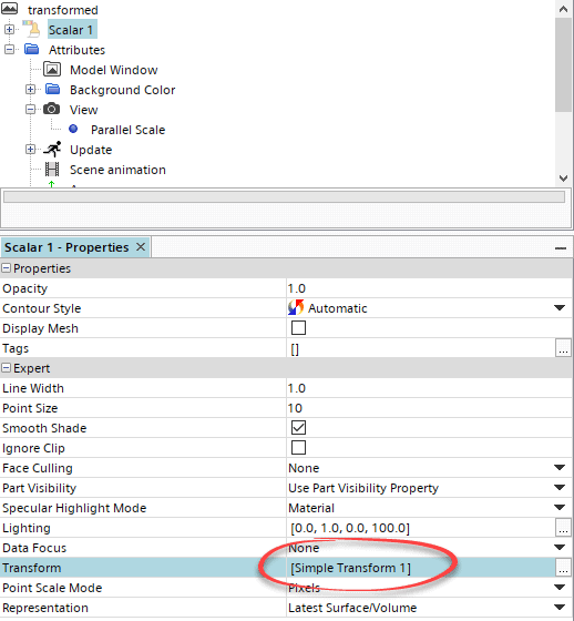
5. Last step is to set the Rotation Angle in the Simple Transform to our rotationHistory report and apply it to the Displayer of our scene
Option 2: DFBI-Superposed Motion
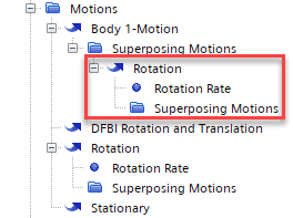
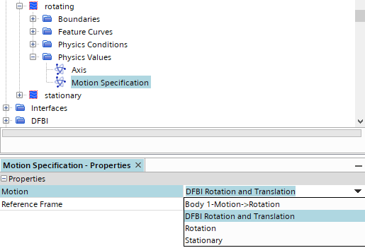
The Enclosed Angle report is, however, restricted to only report positive angles between two Cartesian coordinates. It works fine in case you would like to store information less than ½ of a revolution. Otherwise, you can set up your rotating part with DFBI Motion, fix all degree of freedom and only allow the rotation. Then, superpose the rotation to the DFBI Rotation and Translation and use DFBI Rotation and Translation instead of a Rotation in your rotating region:
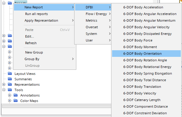
With the DFBI active, we get access to several related reports from which 6-DOF Body Orientation is the that gives us the Euler angles that define the orientation of a body with respect to the initial orientation.
Eventually, we can save the report in the Simulation History, read it through a Surface Average report with Representation of the Simulation History and create the same type of Simple Transform to the Displayer.
Read also:
Finding the center of a circle in Simcenter STAR-CCM+
STAR-CCM+ field function syntax, part 1
STARCCM+ version 2020.3 news-Part 3
S2S radiation in Simcenter STAR-CCM+