Industrial machinery is typically controlled by programmable logic controllers (PLCs), making it essential to verify control software before connecting it to real equipment. By testing PLC logic and system behavior on a digital model using system simulation, engineers can identify issues such as design flaws, inadequate component sizing/selection, faulty control logic, or inefficient control strategies early in the development process. Virtual testing in this manner reduces late‑stage changes and reduces the cost of manual debugging during startup and project build.
Tight collaboration between hardware engineering and control‑system teams is essential in any development. This approach not only compresses the overall development time but, more importantly, ensures that both hardware and software meet quality requirements and prevents any unforeseen issues outside the normal operating range.
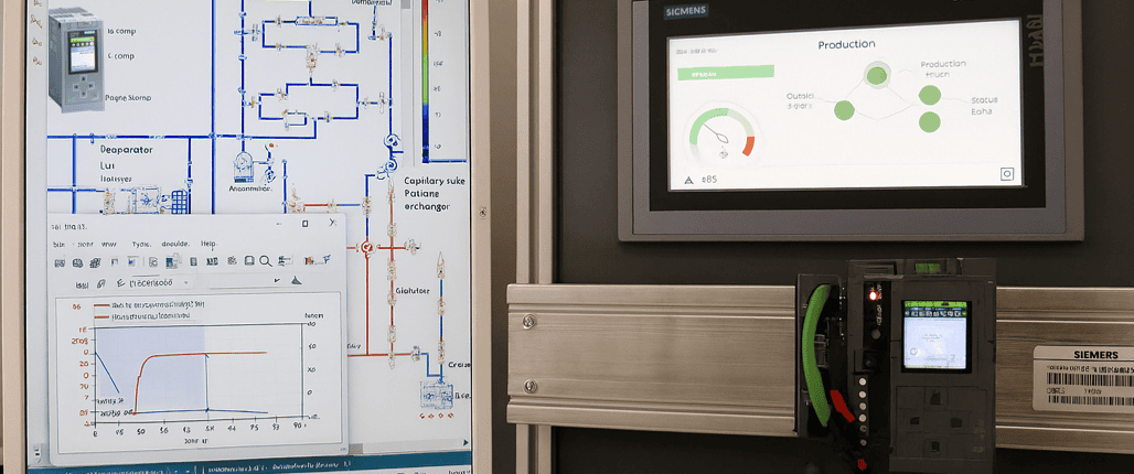
Simcenter Amesim supports a wide variety of domains and physics. The transient analysis capabilities of Simcenter Amesim enable you to investigate both slow thermofluid processes, as well as faster operations found among metal-forming applications or within the field of robotics. When connected to your virtual or real automation equipment, Simcenter Amesim also enables the creation of meaningful human machine interfaces (HMIs) to monitor or interact with a simulation model of your machines.
Investigating the possibilities of creating a connected simulation model to reach product maturity earlier is certainly worth considering.
In this article we will have a closer look at how control logic can be combined with the tools in Simcenter Systems to perform transient simulations governed by virtual PLCs.
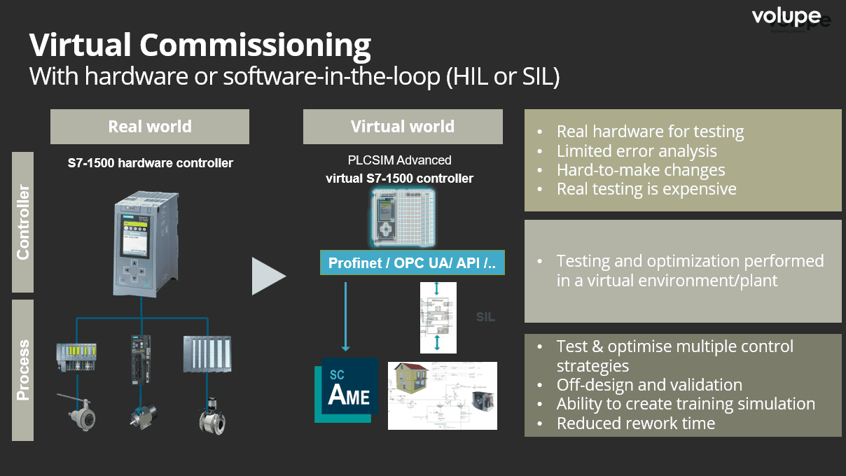
To connect control systems developed outside the Simcenter Systems simulation environment, a bridging tool called Automation Connect can be used. Although strictly speaking not necessity for establishing connections, Automation Connect offers a convenient way to interface Simcenter Amesim and Simcenter Flomaster models with a wide range of real or virtual automation controllers. The tool provides a fast and streamlined way to map and exchange variables between systems. It supports two primary categories of applications: Hardware‑in‑the‑Loop (HiL) and Software‑in‑the‑Loop (SiL). In addition, it also accommodates mixed HiL/SiL scenarios, where only part of the automation hardware is physically present while the remainder is simulated.
Connection with real automation and drive controllers, such as Siemens SIMATIC PLCs, SIMOTION, and SINUMERIK, enables a wide range of HiL applications. Automation Connect also supports Profinet and Profibus communication through a SIMIT UNIT (also known as Simulation Unit), providing reliable real‑time data exchange to hardware. As a more generic interface a OPC‑UA client is also available, expanding the possible integration with a broader range of automation devices. In addition, the tool offers seamless connectivity to SIMIT Virtual Controllers and PLCSIM Advanced, making it possible to integrate both virtual and real control systems.
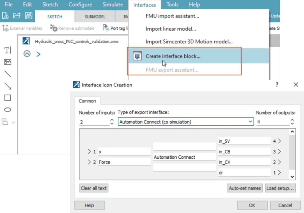
To prepare a simulation model for connection to Automation Connect and a virtual controller, an interface block is added in Simcenter Amesim. Block inputs are the outputs of the Simcenter Amesim model (variables sent to Automation Connect) whereas block outputs are the inputs to the Simcenter Amesim model (variables received from Automation Connect)
Connecting the Automation Connect tool
When compiling the model, a Simcenter Amesim DLL is created in the base directory of your Simcenter Amesim model. This DLL is then loaded into Automation Connect.

After you have selected a Co-Simulation DLL, the tool will automatically connect to Simcenter Amesim and list all defined interface-variables. Automation Connect acts as the co-simulation master and time keeper, and Simcenter Amesim as a slave. Giving you the possibility to control the simulation with Automation Connect.
Next, a maximum simulation time needs to be defined and the simulation manually started from the start/stop button in the Simcenter Amesim tab. While running a simulation, you can interact with your model by reading output variables or writing input variables.
If you are working with Siemens S7-1500 PLCs and TIA Portal, you can emulate your target PLC using PLCSIM Advanced, which then can be connected with Automation Connect.
The video below shows the use of Automation Connect to bridge the connection between PLCSIM Advanced and a system simulation model of a hydraulic sheet metal press. The variable mapping in Automation Connect is also shown as well as how the control logic is used to control the virtual machine during the simulation with an HMI.
When to use wall-clock-time synchronization and when not to?
For Hardware‑in‑the‑Loop (HiL) cases, it is recommended to enable wall‑clock‑time synchronization in your model. Without it, data exchange with real‑time devices such as PLCs will become highly asynchronous. This synchronization can be achieved using the time‑sync component in the Simulation Library.
For Software‑in‑the‑Loop (SiL), however, synchronizing to wall‑clock time is generally unnecessary unless the goal is to create a realistic, real‑time interactive model—typically for operator‑in‑the‑loop scenarios. In most SiL workflows, it is instead preferred to use “virtual time,” allowing the simulation and the controls to run slower (or faster) than real time (RT).
We hope you have found this article interesting. If you have any questions or comments, please feel free to reach out to us at support@volupe.com.
Author
Fabian Hasselby, M.sc.