In this week’s blog post we will take a look at axisymmetric simulations in Simcenter STAR-CCM+. If your geometry and flow field is symmetric around a rotational axis you can use the axisymmetry workflow to save a lot of cells and computational time. In this blog post you will get guidance on the set-up, together with some tips and tricks for your simulations including symmetry conditions.
Geometry for axisymmetric simulations
When working with axisymmetry there are some criteria that need to be fulfilled in order to get a smooth experience in the axisymmetric workflow. If your simulation is based on a geometry that is created from a sketch in 3D-CAD, make sure that you are using this set-up:
- Your sketch should be located in positive X and positive Y coordinates quadrant.
- The set-up is more robust if the underlying geometry you are creating is 90 degrees (one quarter) of a full rotation, and then batching the geometry for 2D meshing (using the operation Batch for 2D meshing) in the operations node within the main GUI tree structure.
- Use the X-axis as rotational axis.
This will make the XY-plane become the plane of the mesh, indicating that you are working in the XY-plane. Below there is a visualization of how a 90 degrees geometry can look like and how it is located in the coordinate system.

Parts and operations for axisymmetry
When creating a new 3D geometry part from your 3D-CAD model you need to use the operatoin “Badge for 2D meshing” in order to obtain a 2D geometry. The same goes if you are importing your geometry directly into the tree-structure, just make sure that the criteria mentioned in the previous section are fulfilled. See picture below for what a part that is badged for 2D meshing looks like. The surface located in the XY-plane (at z = 0) will be the surface used in the simulation and the other surfaces will become curves (which will correspond to boundaries for the region).

Meshing in axisymmetric simulations
In the picture above you see that you need to create an automated mesh operation for 2D meshing to obtain a 2D mesh. The structure is the same as in 3D, but not all features for customizations are relevant when using this mesh strategy, since there is less input required. Below you see a 2D mesh for the geometry used in this blog post.

The 2D mesh operation only supports serial or concurrent meshing, but the element count will generally be low, so the meshing does not use much computational power nor time.
Previously at the Volupe blog we have discussed meshing of models with periodic symmetry, but not axisymmetry. If you are interested in rotational symmetry meshing you can take a look at the previous blog post, using directed meshing, at https://volupe.com/blog-volupe/directed-meshing-in-simcenter-star-ccm/.
Region and continua settings for axisymmetric simulations
In the continua you need to choose the Axisymmetric model, indicating that the transport equations are solved in a simplified manner, to the 2D and axisymmetric conditions. In the region you need to specify which boundary is the axisymmetric, which in this case is y0 (the X-axis). See the picture below for the settings.

Results for axisymmetric simulations
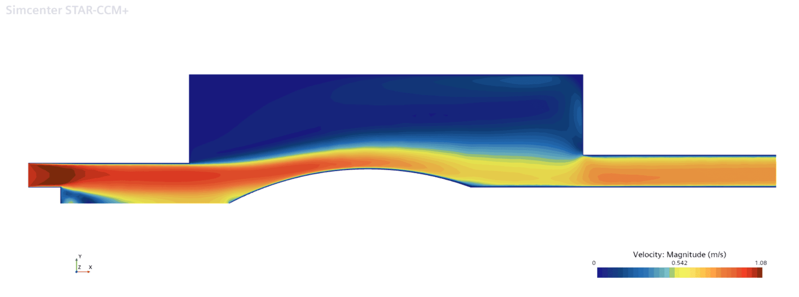
Now, for the visualization of the results. In the picture below you see the velocity magnitude field for the geometry. The flow goes from left to right and before the obstacle in the middle you see that there is a slip condition at the axisymmetric boundary hence no friction on the rotational axis.
Visualization with idealization
The picture above is an okay visualization but Simcenter STAR-CCM+ also provides the capability of Accounting for idealization which means that the rotational symmetry you have used can be visualized as if it was a 3D simulation. In this simulation you will therefore obtain a full cross-sectional view in the scene when enabling this feature. See the picture below for the mirrored image.

When reporting values on an axisymmetric simulation you will have to compensate for the rotational symmetry, if you want to compare with 3D data, and thereby multiply the values from the report with 2*pi (meaning that the calculation is done for a rotational symmetry slice of 1 radian, as when running 2D dimensional simulations the depth is assumed to be 1 meter). This gives that values like pressure etc. do not need to be adjusted, but mass flow reports for example need to be multiplied by roughly 6.283 to get the full 360-degree answer. In the reports there is a check-box to enable accounting for initialization as well as in the scenes. So remember to enable this feature when working with periodic models.
We at Volupe hope that this blog post has been helpful and that you will be able to use the axisymmetric workflow to save both computational cost and time. As always, feel free to reach out to us at support@volupe.com if you have some questions regarding your simulations.
Author
Christoffer Johansson, M.Sc.
support@volupe.com
+46764479945