How does one best design a system intended for ventilating, heating, and cooling a room, a floor, or an entire building? Which components should be used, and how should these be dimensioned to efficiently control the indoor climate when subjected to both internal and external heat sources. The questions raised here are fairly typical throughout most industries dealing with thermal management of any enclosed compartment and in this article we investigate how both Simcenter STAR-CCM+ and Simcenter Amesim can be leveraged to find answers using a smart coupling approach.
To begin with the smart coupling and details concerning Embedded CFD tool inside Simcenter Amesim was covered more thoroughly in an earlier blog post which can be found below (click on the image).

To provide a brief summary of what the tool does in this article, a few things concerning the workflow could however be mentioned.
Firstly, either a more detailed fluid geometry is created of an enclosed volume, or imported by the tool from Simcenter Amesim. Once created, Simcenter STAR-CCM+ is called in the background to create regions, interfaces, boundaries, physics continuum and finally carry out a predefined mesh operation. The model in Simcenter Amesim will then call Simcenter STAR-CCM+ to run steady-state CFD simulations at various intervals. These simulation results are then used to update the model in Simcenter Amesim with regards to internal air mass flow rates and near wall convective heat transfer coefficients. Because of this way of connecting the tools, Simcenter Amesim is able to continue its transient analysis in-between CFD updates using more accurate flow rates and HTCs, and once the enclosed volume’s flow field becomes outdated is able to launch a new CFD simulation to update its values.

For a building HVAC simulation, the division between tools could be done as shown in the image above. Determining duct routing, setting system layout, dimensioning components and simulating the effects of different cycles over days or months is commonplace in system simulation, but becomes impractical and computationally expensive using only a CFD tool. At the same time, having a way of directly assessing the impact of a system change on the thermal comfort in a room, or set of rooms, opens many new doors, and is why such an analysis can benefit from coupling the tools.
In the case study featured in this article, a model of an office floor was created in 3D-CAD (Simcenter STAR-CCM+) and used as the enclosed volume in Embedded CFD. The floorplan is provided below showing office spaces in different directions. The rooms are separated from each other with closed doors, and in each room an air inlet placed on the floor (blue circles), and air outlets in the ceiling (pink rectangles). Most offices have one or two windows, as well as radiators placed below them (yellow rectangles).
In Simcenter STAR-CCM+ the separate rooms are formed into a single region, but the individual air volume does not interact. Here Simcenter STAR-CCM+ essentially runs different steady simulations at the same time. Boundary conditions are selected from the Embedded CFD tool in Simcenter Amesim.

Compared to other thermal comfort studies done in Simcenter STAR-CCM+, the intention with the CFD model used here is to be able to run it for very long transient runs without the simulation ending up becoming impractical. In order to achieve this a more “light-weight” approach is taken for the underlying CAD, containing fewer detailed features. In the scene below, both people, furniture and equipment were simulated with high detail. Given the low inlet velocities it is reasonable to expect that similar results for flow field velocities or average room temperatures could be achieved if the people were replaced with cylinders and furniture with box shapes instead. As always it depends on the purpose of the simulation, and for a coupled approach with the intention of designing a HVAC system, variation in average temperature between rooms over time might be more important.

The final light-weight mesh of the office floor using a base size of 0.2 [m] is shown in the image below. The total cell count amounted to roughly 120 000 cells, which preserves many of the basic room shapes, such as doors and windows, and inlets and outlets. Highlighted in pink is one several volumes extracted from Simcenter STAR-CCM+ and later used in Simcenter Amesim to calculate flow characteristics and temperature behavior between CFD runs. Increasing the number of flow volumes has a large impact on the time needed to generate the final sketch in Simcenter Amesim, therefore the number of cutting planes in the Embedded CFD tool was kept low in this study.

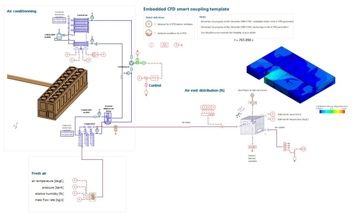
The study was configured so that the distribution of fresh air supply between the various inlet ducts in the building was determined on the system simulation side. The AC system delivering cooler air to the rooms was modelled using components from the Air Conditioning library, describing the full thermodynamic cycle as well as each component specification. Ambient conditions such as external temperature and solar influx using the suns relative position was determined in Simcenter Amesim during a 24 [h] long transient simulation. Simcenter STAR-CCM+ was called to rerun its CFD analysis if the room’s average temperature increased or decreased by 2 [°C]. To control the AC system a crude PID controller compared the difference in temperature to a set value of 20 [°C] and controlled the compressor speed of the system. Below, the model in Simcenter Amesim is given.
The 24 [h] long simulation took roughly 10 [min] to complete and the CFD simulation was distributed on five cores during the run. Below, a few pre-defined result scenes from Embedded CFD are show. Here the velocity near walls, surface temperatures, vector plots and stream lines provide a picture of what is happening within the different rooms.

To investigate how well the intended AC-system, and accompanying control logic, managed keep the indoor climate close to the desired temperature setpoint of 20 [°C], the average room temperature was plotted over the entire 24 [h] simulation run. As seen, the system has a difficult time of maintaining low temperatures once the sun rises at 9 am until it sets again at 6 pm. (During the initial portion of the simulation all rooms were rapidly cooled down since the initial room temperature had been set to 30 [°C]). Also plotted alongside the temperature are the times when the CFD solver was called to perform its steady-state simulation to update the values inside Simcenter Amesim.

We hope you have enjoyed this article, and have better luck with designing your building HVAC system than we ended up having! If you have any questions or would like to know more on the topic of coupling Simcenter STAR-CCM+ and Simcenter Amesim, please feel free to reach out to us on support@volupe.com
Author
Fabian Hasselby, M.Sc.
