In CFD simulations involving several parts, such as conjugate heat transfer (CHT) or Fluid-Structure Interaction (FSI), you need to establish a connection between the different parts to enable exchange of data. This connection is typically handled through an interface. In Simcenter STAR-CCM+ interfaces can be of either boundary-mode or contact-mode type. In this week’s blog post we will focus on the contact-mode interface and some important considerations for the different sub-categories that are available.
Connectivity and contact types
The main differentiator between the two interface types is that a boundary-mode interface is established as a single direct connection between two boundaries, while a contact-mode interface can establish a connection between entire parts, involving several boundaries on each part. As such, the contact-mode interface is numerically more efficient, as it rationalizes the interface interpolation process, and is hence the recommended interface type to use in Simcenter STAR-CCM+. Especially when handling multiple contacts. For more information on the different interface types, please refer to our previous blog post How to work with interfaces in Simcenter STAR-CCM+ – VOLUPE Software.
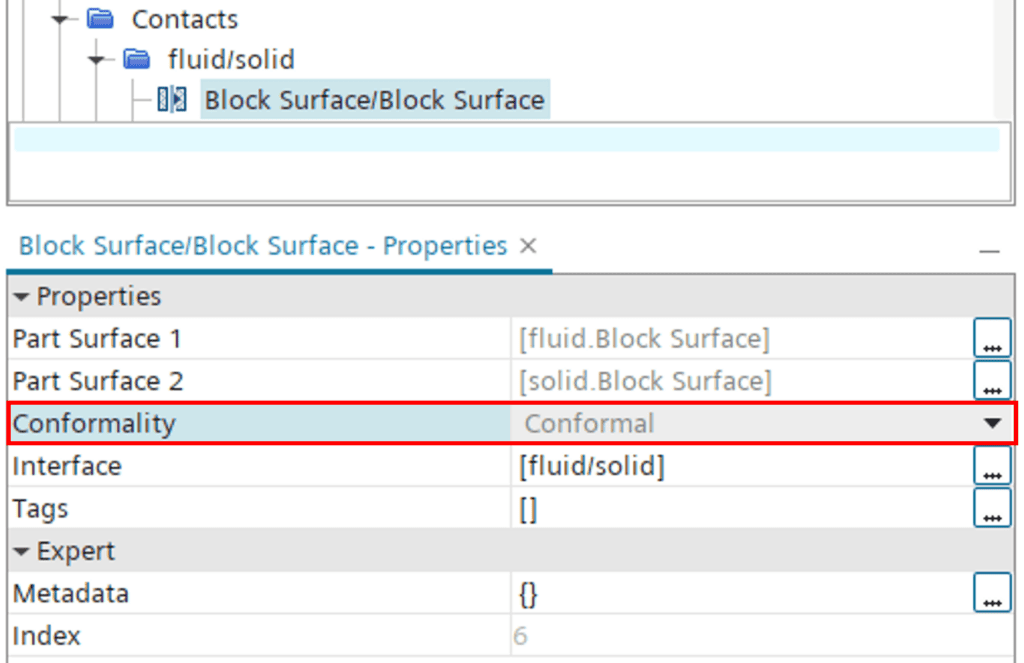
Contacts (or in-place contacts) in Simcenter STAR-CCM+ can be of two different types: strong or weak. A strong in-place contact indicates that different parts are coincident and allows you to generate a conformal mesh between the two parts, whereas a weak in-place contact does not. Both types of in-place contacts become interfaces when you assign the parts to regions. You can see whether an in-place contact is strong or weak by checking the Conformality property of the contact. If the conformality states “Conformal”, the contact is strong.
Contact-mode interfaces can be established with three different types of connectivity:
- Conformal contact with imprinted connectivity
- Non-conformal contact with imprinted connectivity
- Non-conformal contact with mapped connectivity
In the following sections we will go through these different types in more detail.
Conformal interfaces (strong in-place contacts)
A conformal interface means that two separate parts share the same vertices at the interface (i.e. a 1-1 match between nodes).

Conformal interfaces are generally the most desirable since there is no need for interpolation, reducing the risk for numerical errors. To achieve conformal interfaces in STAR-CCM+, the following requirements apply:
- Strong in-place contacts (conformal high-fidelity CAD or imprinted contacts)
- Ingoing parts must be in the same mesh operation
- Per-part/Concurrent meshing must be disabled
- Polyhedral or Tetrahedral mesher must be used
The bottom three requirements are easily met through selections in the mesh operation setup, but how do we make sure that we have strong in-place contacts?
Ideally, you want to make sure that you have a high-quality CAD with coincident geometries, then make sure the option “Create Part Contacts from Coincident Entities” is ticked when you import the parts into 3D-CAD.

If, for any reason, you would still be missing any contacts, you can also imprint the parts that should be coincident with a Boolean operation in 3D-CAD.
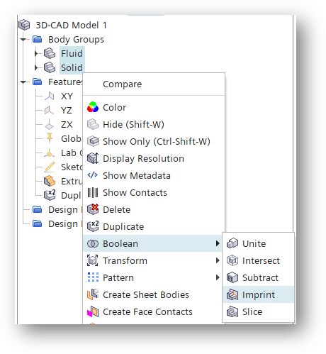
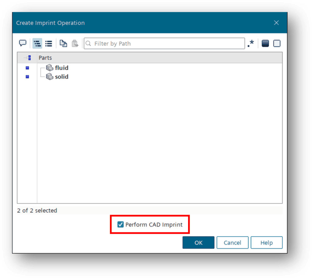
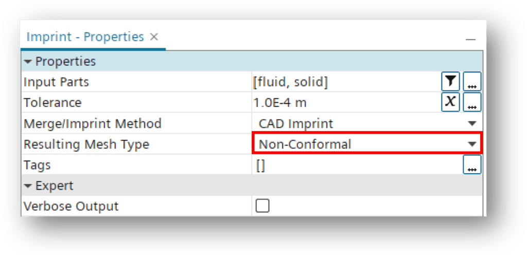
Alternatively, you can pipeline the contact creation by using a Boolean Imprint operation within the geometry operations in the simulation tree. Make sure to use the option “Perform CAD Imprint”.

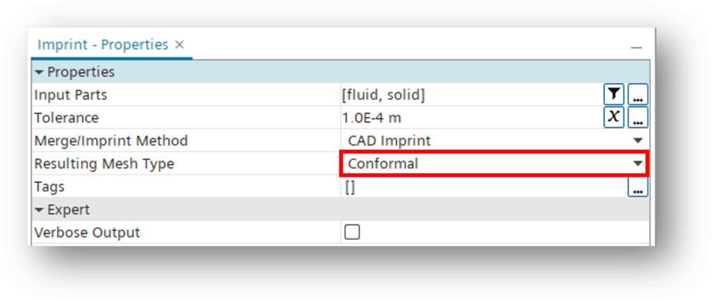
Also make sure that the Imprint property “Resulting Mesh Type” is set to Conformal.
If you are not importing into 3D-CAD, but rather are working directly with a tessellated geometry, you can also use Discrete Imprinting to establish strong in-place contacts. Discrete imprinting allows for slight movement of faces to make them coincident – hence it is highly dependent on tessellation density and tolerance. A higher tessellation density typically improves the quality of the imprint. The Discrete Imprint can obviously be conformal, but it could just as well be chosen to create non-conformal contacts.


Non-conformal imprint interfaces (weak in-place contacts)
So, what if it’s not feasible to create conformal interfaces? Perhaps the geometry is too complex or maybe the CAD is of low-fidelity? Or perhaps you want to utilize per-part or concurrent meshing to maximize productivity? Don’t worry, you can still achieve an acceptable connectivity using non-conformal imprint instead!
To create a non-conformal imprint, you select Non-Conformal in the “Resulting Mesh Type” for the Boolean imprint operation. This will create a so-called weak in-place contact.
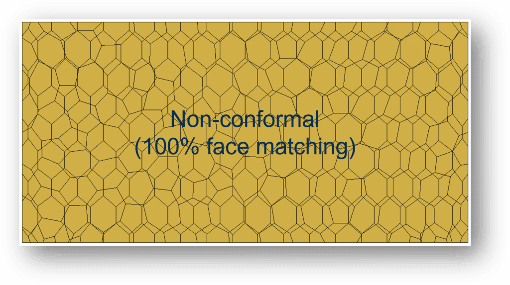
Using Non-Conformal imprint, Simcenter STAR-CCM+ will split the interconnecting faces to create matching vertices on each side of the interface (see pictures below).


As the imprint operation will attempt to form matching pairs of faces on the interface, it is important to aim for similar mesh resolution on each side of the interface. If there are large discrepancies or gaps the algorithm may not find a match. Any unmatched faces will not be included in the interface data transfer and instead be treated as walls. The face matching of the interface is always quantified and reported when initializing the interface, e.g:

The matching can also be visualized in a scene (where yellow faces indicate a match, see examples below).

The higher the match, the better the results of the data transfer. If you are experiencing a bad face match, you can try either increasing the imprint tolerance or increasing the interface intersection tolerance (see pictures below).
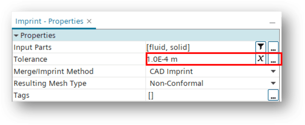

Please note that if you need to go higher than 0.1 in intersection tolerance, you should probably consider repairing the geometry, or use a mapped contact interface instead (see next section).
Non-conformal mapped contact interface (weak in-place contacts)
In contrast to a non-conformal imprint, a mapped contact interface does not intersect faces to create shared vertices. Instead, it uses a proximity-based data mapping to calculate the data transfer (see example on connectivity below).

Mapped contact interfaces are useful for geometries where you cannot achieve a good face match (>98%), even with non-conformal imprint, or when you wish to use different mesh resolutions on each side of the interface. As it is only proximity-based, it allows for slight gaps or even overlaps in your geometry.
As mentioned earlier, conformal meshes are often the most desirable. But as a matter of fact, there may be cases where a non-conformal mesh will actually make the most sense. For instance, the heat conduction in a solid region typically requires a coarser mesh compared to resolving the boundary layer and gradients in a fluid domain. By excluding the need for conformality, a non-conformal approach can therefore retain a high-quality mesh in the fluid, while still minimizing the total cell count in a CHT simulation.
Just as non-conformal imprint, the mapped connectivity is compatible with per-part and concurrent meshing. To create a mapped contact interface, you simply switch the “Type” under Interface properties to Mapped Contact Interface (see below). When doing this, you will see that the connectivity changes from Imprinted to Mapped.

I hope this summary will be helpful when working with interfaces in Simcenter STAR-CCM+. As always, if you have any questions or comments regarding the blog, please reach out to us at support@volupe.com.
Author

Johan Bernander, M.Sc.
Application Specialist