In this week’s blog post we will highlight the so-called “Expert” properties of the Automated Mesh operation in Simcenter STAR-CCM+. We will look at the features Perform Local Meshing and Preserve Surface Perimeters and use a wind turbine blade as our reference geometry to exemplify the different features.
The wind turbine blade
The reference wind turbine blade used in this example has been divided into ten different segments (or patches) by renaming faces in 3D-CAD. The blade is one single closed body, but with five named faces for the pressure side and five named faces for the suction side. There is also a “Default” named face which contains the hub and the blade tip.


Before applying any of the Expert properties, we assign the blade to a region and mesh it with a base mesh using default settings. Since all faces of the blade are walls, we will assign them all to one single wall boundary. This is the recommended way of working in Simcenter STAR-CCM+, since it is most efficient from a solver perspective to keep the number of boundaries to a minimum.

The base mesh created using this setup can be seen in the picture below (colored by input). As you may note, the surface mesh on the blade overrides the feature lines separating the different patches.
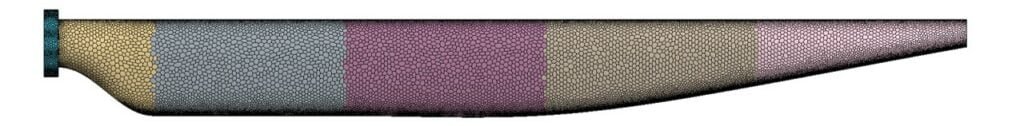
Usually this is preferable, since you don’t want feature lines to cut through elements, potentially creating low-quality cells. But let’s assume you would like to quantify something on the different segments of the blade (e.g. a lift or a drag force). In such a case you would probably want to retain the distinct separation lines between each patch. One solution would then be to put each different patch into a separate wall boundary (since the mesher respects separation lines between boundaries). But remember, increasing the number of boundaries also increases the load on the solver, increasing simulation time. This is where the Expert property Preserve Surface Perimeters comes to use.
Preserve Surface Perimeters
So, let’s see how we can make use of this setting. First off, we find the setting in the properties for the Automated Mesh operation (see picture below).

The default setting is to preserve none of the surface perimeters, which is what gave us our base mesh where the feature lines were overridden. Now, to retain our feature lines between the surface patches (while still having them in the same boundary) we have three different options:
- Major Mesh Controls Surface Perimeters
Maintains the surface perimeters for surfaces to which you have applied custom surface controls for the prism layer mesher only. - All Mesh Controls Surface Perimeters
Maintains the surface perimeters for all surfaces to which you have applied custom surface controls. - All Part Surface Perimeters
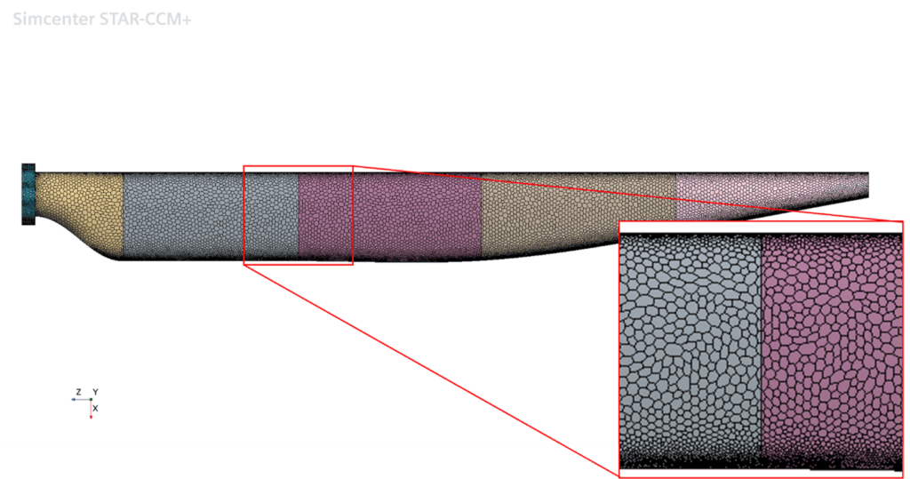
In this example, we don’t have any custom controls setup, so we will select All Part Surface Perimeters. Once we have made the selection, we execute the meshing operation again. The result from this operation is shown in the picture below. Now we have successfully created a mesh where the surfaces are distinctly separated from each other, while still belonging to one single wall boundary.
Perform Local Meshing
The other “Expert” property we will investigate is the local meshing feature. To demonstrate this feature we will once again start with our base mesh, where we have a somewhat uniform distribution of the element sizes on each segment of the blade.
Now, let’s assume we decide that we want to refine the mid segment for some reason. What we could do is to add a custom control and then remesh the entire blade. But a more efficient option could be to make use of the Perform Local Meshing feature. Please note that local meshing requires a base mesh as a starting point.
We start off by ticking the box in the Expert properties panel (see picture below). The Automated Mesh entity now receives a modified icon, with a blue circle, indicating that we have activated local meshing on the operation.

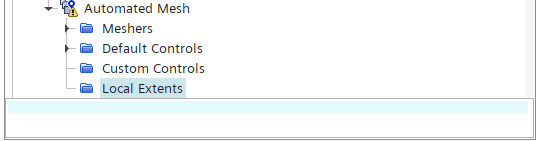
Now we move into the Automated Mesh operation and notice that the entity has also been populated with a new folder; Local Extents.
Local Extents can be either surface based or volume based:
- Surface Extent
Accepts a set of part surfaces that define the remeshing zone. When used with volume remeshing, the mesher extracts volume extents based on the selected surfaces. - Volume Extent
Accepts any part within the simulation that defines a volume. When used with volume remeshing, the mesher extracts volume extents based on the selected surfaces. For surface meshing, surfaces within the volume are candidates for remeshing.
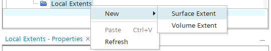
So, the way you use the local meshing is by defining either surface extents or volume extents (or both) for the areas that you wish to remesh. In our example, we choose to create only a surface extent for the mid segment of the blade. To create a surface extent we right-click the Local Extents folder and select New -> Surface Extent.
Once we have our Surface Extent we move into the properties and select our input surfaces. In this case, those are the mid-most surfaces of the blade. The Inflation Distance and Inflation Layers are settings describing how the local remesh will adapt to the original, surrounding mesh. Inflation Distance gives you the possibility to define an offset from the extent up to where the surrounding mesh will be affected by the local mesh. The Inflation Layers work in a similar way, but the offset from the extent is in terms of number of elements, rather than explicit distance.

In this example we let the local mesh extend 0.1 meters into the surrounding mesh. After setting up the properties for the local mesh, you redefine the settings for the mesh operation inside the regular controls (i.e. Default Controls and Custom Controls). The difference now is that the updated settings will come into effect only for the Surface Extent when you execute the operation. Here we decided to simply lower the base size from 0.05 meters to 0.025 meters. Then we reran the mesh operation. The resulting surface mesh on the blade is shown below.

I hope this blog post has been useful in showcasing what you can do with the Expert properties for the Automated Mesh operation. As always you may send in comments or questions to support@volupe.com.
Author

Johan Bernander, M.Sc.
Application Specialist