Creating the right mesh for your numerical analysis is one of the trickiest tasks! In Simcenter STAR-CCM+ we have Custom Controls allowing us to create beautiful meshes with refinements wherever we expect stronger gradients to be solved. One of these refinement methods is the Anisotropic Meshing for Advancing Layer Mesher (https://volupe.com/blog-volupe/simcenter-star-ccm-2021-3-news-part-1), which needs part curves as input. Let´s have a look on a new feature that helps you to create those part curves where needed in Simcenter STAR-CCM+´s Surface Repair tools.
Application of anisotropic meshing for a cavitating propeller – the flow compares well to the experiment both qualitatively and quantitatively
The new edge offset and imprint tool inside the Surface Repair tool allows you to create new edges at some offset distance from an original input set of edges or curves. Alternatively, you can also use an interactive sketch tool to sketch the curve on the destination surface.
Edges are automatically imprinted onto the target surface using the edge to face imprinter. The new edges can also be automatically flagged as curves if desired, so that a new part curve object is created for the part.
How to create part curves in a marine propeller
Let’s have a look at a practical example. Sometime when we import a geometry, we can see that we don’t have any part curves. Sure, we can compute part curves but then all curves end up in a single part curve and need to be sorted and combined according to our needs for meshing.
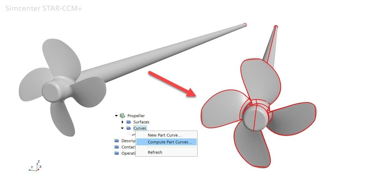
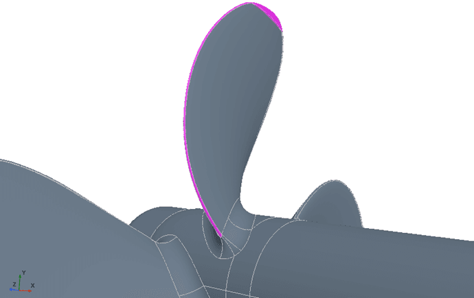
In case of the MV Regal propeller we have surface patches along the leading and trailing edges. Which means we would not get curves at the outermost front and back of the blade from computing edges.
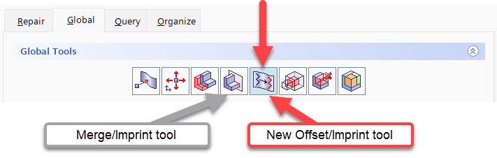
First, we open the Surface Repair tool and select the Offset/Imprint tool from Global Tools tab. Since the tool performs as an imprint the overall look and feel of the panel is similar to the other imprint tools in Surface Repair.
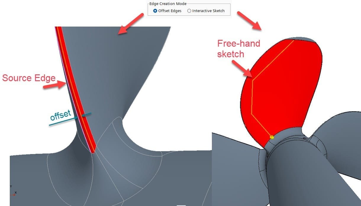
Either, we select Offset Edges or Interactive Sketch mode. For the offset tool we need to specify Source edges and Destination faces in the subset tool functions. For the sketch mode we only need the Destination faces.
Offset Edges
The tool operates in three modes:
- Coordinate Offset—allows you to offset edges based on a relative coordinate offset value, for example projecting edges 2mm in the X-direction.
- Projection Offset—allows you to project each source edge based on either the shortest distance between the source edges and destination faces, or a specified coordinate direction between the source and destination.
- Geometry Offset—allows you to project each source edge based on the local vertex conditions. The Geometry Offset mode has the distinct advantage of performing multiple projections in one operation since the projection direction is implied from the destination faces and not a single coordinate direction.
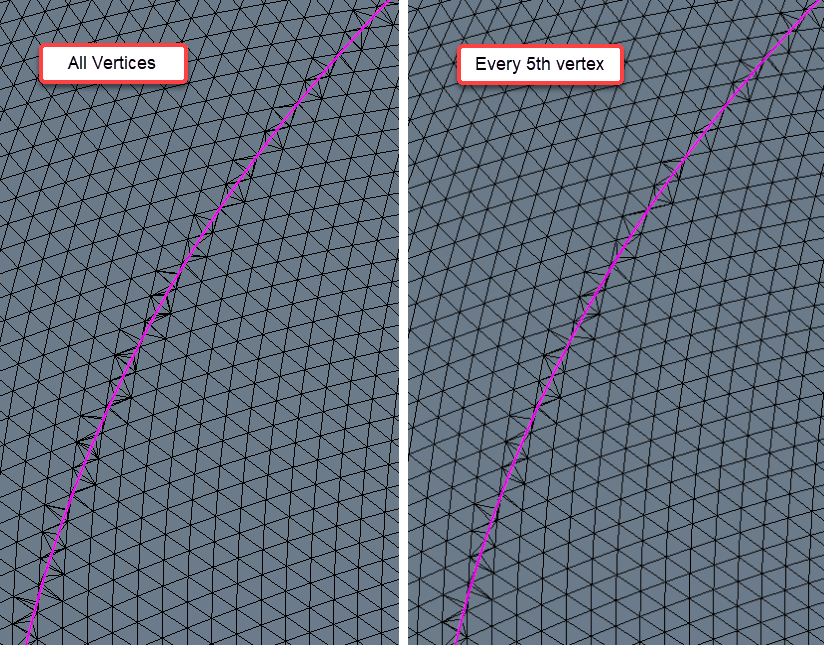
For good quality surfaces the default behavior (All Vertices) gives the most consistent results in terms of the continuity/smoothness of the projected edges. However, the other sample rates can be more appropriate depending on the local face quality and variation of triangle size from one face to the next. As more vertices are skipped, the chances of encountering inverted edges (those that cross over each other in the result) decreases.
Additionally, a Preview option is included that allows the results of the initial edge projection (but not the edge imprint) to be visualized prior to the offset operation being executed. This is useful to verify if the input values are appropriate plus also run all the pre-checks on the input subset requirements (more details below) prior to the projection being performed. For complex or organic geometries doing a preview is a must and can save a lot of time and effort when attempting to generate a result.
Interactive Sketch
The interactive sketch is . The only input needed are one or more Destination surfaces. Once selected you can go ahead and Start Sketching. The only restriction is that sketches can only consist of straight-line segments.
![]()
With the new edges we can finally control the meshing of our geometry. We at Volupe hope that you find this explanation of the new feature useful for future projects to control the mesh generation with more flexibility. Please let us know your thoughts, comments, and questions at support@volupe.com.
The Author
Florian Vesting, PhD
Contact: support@volupe.com
+46 768 51 23 46