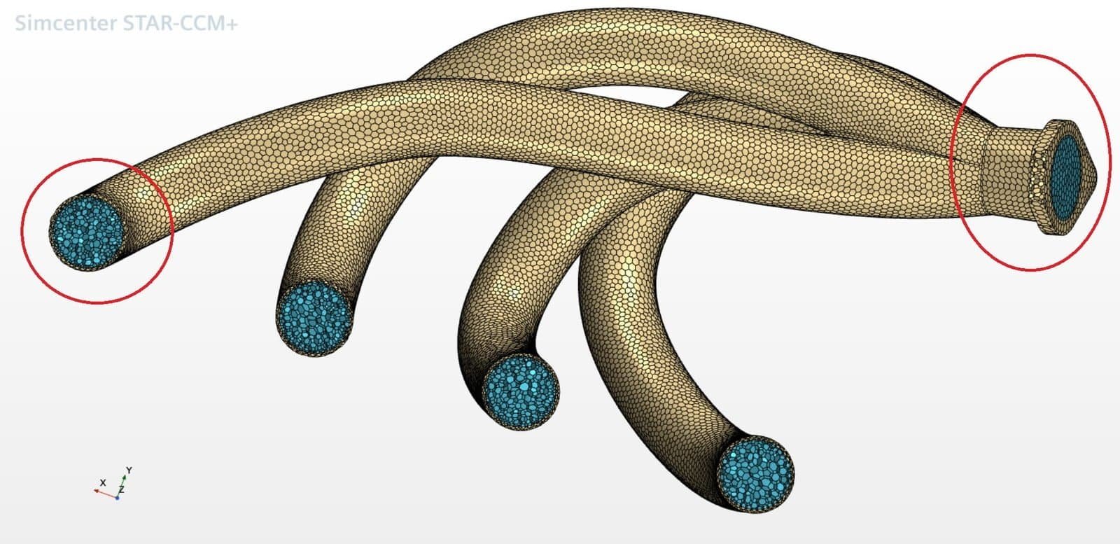
In this week’s blog post we will look at the remaining expert features from the blog post – Thin mesher in Simcenter STAR-CCM+ part 1. In the previous blog post we used an exhaust gas manifold geometry to visualize the settings available for the thin mesher, so we will continue to use that geometry. The two areas of the geometry which we will use to visualize the settings are one of the runners (to the left in the picture below) and the outlet (to the right in the picture below). The solid (beige color) is 2mm thick at the runner and 3mm thick in the flange at the outlet.
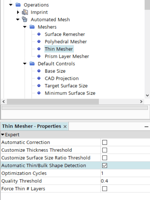
In the thin mesher settings, see picture below, you can enable the Automatic thin/bulk shape detection.
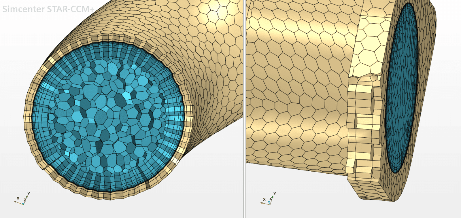
If this option is activated Simcenter STAR-CCM+ will determine if areas of your geometry are thin or not – automatically. If this option is not activated, the whole geometry is considered as thin, so by activating this option some areas might be switched to use bulk mesh cells instead. See the picture below for the result using this setting – the runner is considered thin and the outlet flange is using bulk mesh cells.

If you would like to have better control over your thin mesh, and use settings to specify criteria for where the thin mesher should be activated and not, then you there are other settings as well. Today, we will look into the Customize surface size ratio threshold. This setting is dependent on the local surface mesh size, at the surface of interest, compared to the solid thickness. In our example simulation, the mesh size of the surface is 2.5mm at the runner and 3mm at the outlet flange. The solid thickness at the runner is 2mm and at the outlet flange 6mm. The setting is defined such as that any part/body thinner than the specified value multiplied with the local surface size will be considered thin by the mesher.
One thing to mention is that is setting is a compliment to the feature Customize thickness threshold, discussed in the previous blog post. So, these two features should be used together, and both of the criteria should be fulfilled in order to obtain a thin mesh at the location of interest.
Assuming that the customized thickness threshold is set to a larger value than both the runner and outlet flange of this geometry we can now look at the settings for the Surface size ratio threshold. If the value specified for the Surface size ratio threshold is below 2/2.5 (equals 0.8, in other words – the solid thickness for the runner divided by the surface mesh cell size at this part) you will not get any thin parts for this example. If the specified value is between 2/2.5 (equals 0.8) and 6/3 (equals 2), you will get the runner as thin and the outlet flange with bulk cells. And if you use a value above 6/3 (equals 2) you will get both the runner and the outlet flange as thin parts, see picture below. In this way you have more flexibility to specify where thin mesher should be used or not.
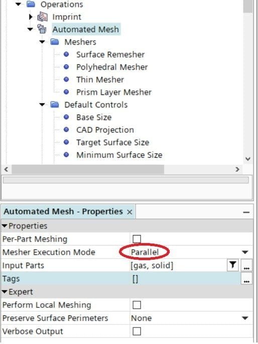
P.S. Do not forget to use the thin mesher in parallel mode, to utilize all your cores available. This possibility was added in version 2021.2 so hopefully all of you have updated your software so you can benefit from this update.
We at Volupe hope that this extended blog post regarding the thin mesher has been interesting. Since tomorrow is a national holiday in Sweden we will post this blog post today, wishing you all a nice weekend (a long one if you are also off work tomorrow). And as always, do not hesitate to reach out to us at support@volupe.com if you have any questions.
Author

Christoffer Johansson, M.Sc.
support@volupe.com
+46764479945