In this week’s blog post we are going to look into the derived parts for warping: scalar, (m’,theta) and vector warp. These warp parts are different types of derived parts using one geometry part as input and modifying the geometry with a specific transform. One extra feature for vector warps is that they can be used for creating a new modified geometry part based on the warping. Vector warps are therefore generally used in FSI simulation for visualizing geometry deformation, while Scalar warps and (m’,theta) warps are often used to visualize physical values.
Scalar warp
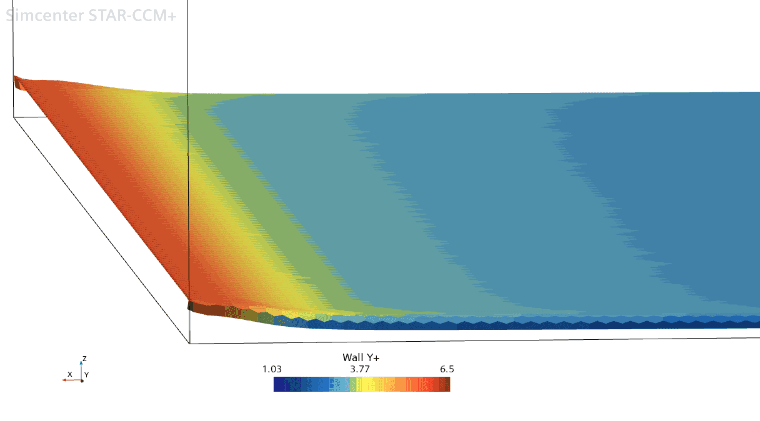
Scalar warps are usually used to visualize mechanical deformations or to scale other results in the visualization. For warping, point coordinates on the surface are used as input and then scaled along a vector normal by the quantity of the specific scalar field. When using other field functions as scale factor the results can look like in the picture below, where the bottom surface of a channel is warped by its Wall Y+ value.
(m’,theta) warp
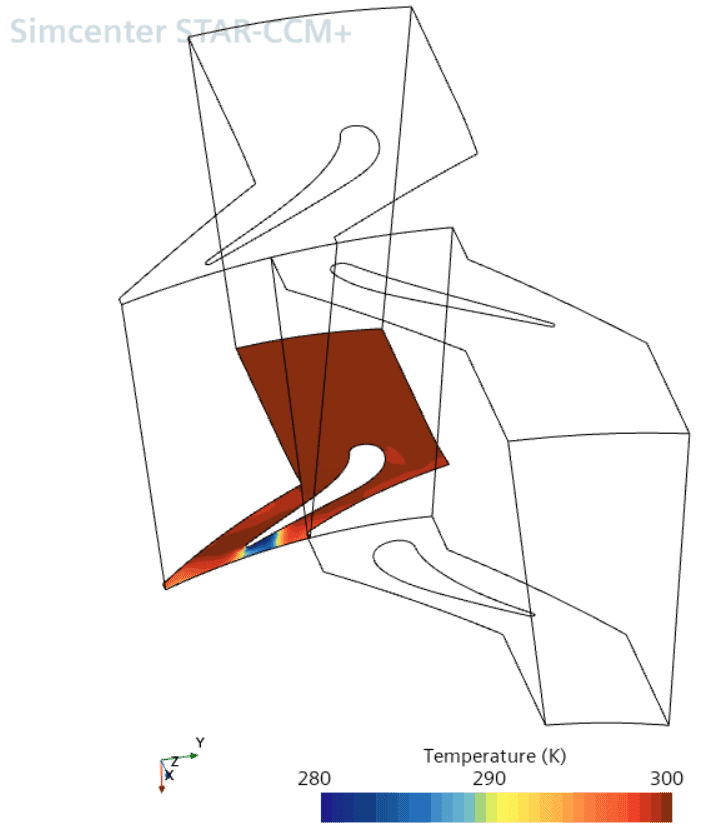
(m’,theta) warps are often used to flatten out a surface which is curved for a clearer visualization. Turbomachinery applications is a good example where this can come in handy, when for example blade-to-blade spans are visualized. By specifying origin of the rotation axis, rotation axis and tangential axis – the warping provides a flat surface where field functions can be visualized. The parts included in the warping need to have one continuous curve for the resulting warp surface to be only one surface, otherwise the warp will be generated to several surfaces. In the example below you find results from a stator hub.
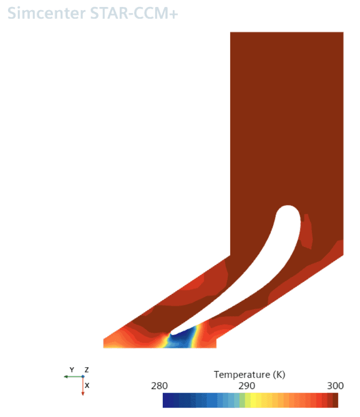
In the picture below these stator hub results are being transformed into a flat surface by the (m’,theta) warp.
Vector warp
Vector warps create surfaces which are based on the selected vector field and then scaled by a scale factor. The scale factor value is usually set to 1 or 0 based on if the scaling should be performed or not, where 0 uses the field function unscaled. A larger scale factor value than 1 can be used, but such a value can often provide a deformation that looks too large. The derived vector warp part can then be extracted as a geometry part, which can be used as input for a deformable part in FSI simulations. The scale factor multiplies the vector field used as input to the derived part.
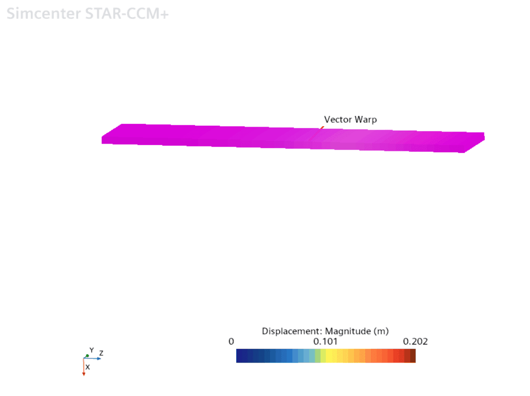
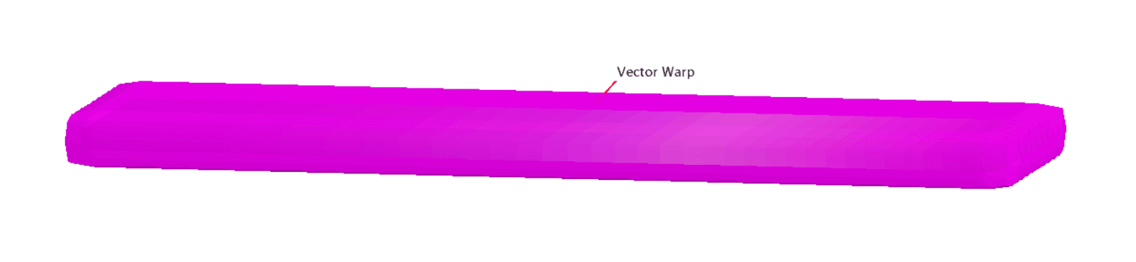
In the example below a plate which is fixed at the left side and free at the right side, with a point load pushing down the free end, is used. The vector warp will look as in the picture below where the warped part is at the same location as the deformed geometry. Note that the displacement is relatively small, and it is therefore difficult to tell that the deformation is visualized.
In the properties for the vector warp, you have several options of how to scale the part. You can choose between relative or absolute coordinates for the warping, referring to the deformed (relative) or the non-deformed (absolute) state. The scale factor can be set manually or enabled as auto-scaling. Siemens recommends only using scaling if the deformations are small, meaning below 5%, since the scaling can be misleading otherwise. When it comes to the vector field, using displacement is only available after the calculation is performed, while normal and position can be used before the calculation. In some simulations it can therefore be better to use normal or position if possible.

The displacement in the example will result in the highlighted warp part in the picture below.

If you scale the normal with a scale factor you will obtain a vector warp which provides a plate thickened in each direction, as seen in the picture below. This vector warp can for example be used as overset region or volumetric control refinement.
To summaries the combinations of settings (for field function, relative/absolute, scale factor value) will result in:
- Displacement, relative, 1.0 => The displaced part warped after displacement occurred.
- Displacement, absolute, 1.0 => The displaced part warped from the initial state.
- Normal, relative, 0.0 => The displaced part.
- Normal, absolute, 0.0 => The non-deformed part (original part).
- Normal, absolute, 0.02 => Offset body.
We hope that you enjoyed this blog post. During the summer months we will re-post some popular blogs from this year, maybe you missed some of them so keep an eye out during the vacation. If there are any questions you are always welcome to reach out to support@volupe.com.
Author
Christoffer Johansson, M.Sc.
support@volupe.com
+46764479945