We at Volupe strive to be able to give you (all the simulation engineers out there) the best support possible. Therefore, we have created a y+ calculator at our webpage, linked here: Volupe’s y+ calculator.
This y+ calculator is the first published content in our own handbook for engineers, to which we will add further functionality that is useful for engineers in their daily work.
This week’s blog post will describe the purpose of using a y+ calculator, features in Volupe’s y+ calculator and how to use the y+ calculator (together with some tips) when deciding mesh settings.
Summary of tips from the blog post:
- The y+ calculator is divided into four parts. If you determine the mesh settings in order part 1 to 4, you will automatically obtain the calculated outputs as inputs in the following steps.
- You can of course use each part of the y+ calculator independently as well.
- Use the calculated boundary layer thickness in part 2 to have a value to aim for in part 3 for the prism layer total thickness.
- How to define your prism layer mesh, dependent on your prism layer distribution mode in Simcenter STAR-CCM+.
- Make sure your transition between the prism layer mesh and the bulk mesh is smooth, by defining your base size close to the value of the last prism layer cell height.
- For the bulk mesh cells adjacent to the prism layer mesh, make sure you obtain cells with high aspect ratio by defining the surface mesh target size to the value of the last prism cell height.
What is a y+ calculator?
A y+ calculator is a way of determining the height of the first cell by the wall in a CFD simulation based on overall settings in the simulation and the desired y+ value. Since the velocity, when you use the no-slip condition to a stationary wall, is zero at the wall, but non-zero in the fluid domain, you get large gradients in the velocity field close to walls. These gradients need to be resolved, in order to get an accurate solution close to the walls. This y+ calculator will help you to determine both the first cell height at the wall, and setting all other properties for the mesh as well, to obtain a good mesh at the first try. The process of creating a mesh for CFD simulations is very delicate and several settings must harmonize. This can be an iterative and time-consuming process, but hopefully we can help you save both time and increase the overall quality of the final mesh with our y+ calculator.
Description of all parts of Volupe’s y+ calculator
The calculator is divided into 4 parts (each part is described in a section below, with a picture of the default settings used on the webpage):
- First cell height in prism layer
- Boundary layer thickness
- Settings for the prism layer mesher
- Transition from prism layer to bulk mesh
First cell height in prism layer – here you give input about your fluid characteristics, to obtain a cell height for the cell closest to the wall, for a desired y+ value. You will also get the value for kinematic viscosity and Reynolds number, since this might help you verifying that the values you have used are correct. The default value for density and dynamic viscosity is based on air at 20 degrees Celsius. You can select if your simulation is for internal or external flow, there is a slight difference in the equations used depending on the type of flow.
The illustrations to the right in the picture below are there to helping select the correct characteristic length.

Boundary layer thickness – By specifying if you have boundary layer that is laminar or turbulent in your simulation, you get a value for the thickness of the boundary layer. The default values for the input parameters in this part (length downstream to evaluate and Reynolds number) are updated automatically from part 1 of the y+ calculator. The parameter length downstream to evaluate, uses characteristic length as default value. The equations that are used to determine the boundary layer thickness are based on flat plate theory. This means that the boundary layer thickness has a linear dependence of the length downstream to evaluate. If the region where you want to estimate the boundary layer thickness does not have flow similar to flow over a flat plate, this estimation will be less accurate (then it can be wise to run a test-simulation to get a better approximation of how thick the boundary layer is, and use the calculated value as input from parts 2 of the y+ calculator).
The illustration to the right, in the picture below, a typical profile for laminar and turbulent boundary layer is visualized.

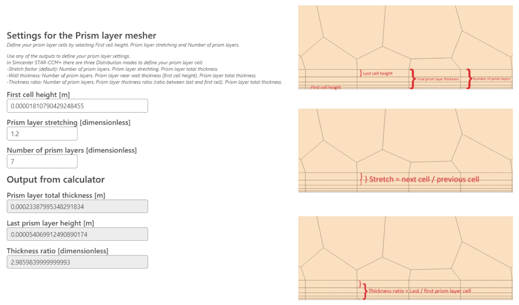
Settings for the prism layer mesher – in Simcenter STAR-CCM+ there are three different distribution modes (ways of defining parameters) to specify your settings for the prism layer mesher. The same resulting mesh is possible to obtain regardless the choice of distribution mode. By defining first cell height (automatically updated to the value from part 1 in the calculator), prism layer stretching (also known as growth rate) and number of prism layers – the output is given so that you can copy the parameter values directly into your simulation software, regardless of which distribution mode you selected. You will also get the value of the height for the last prism cell, since this value can be good to know in the next step, part 4.
The text in the picture below describes which parameters are required to specify, depending on which distribution mode that is selected. In the illustrations to the right the parameters are visualized.
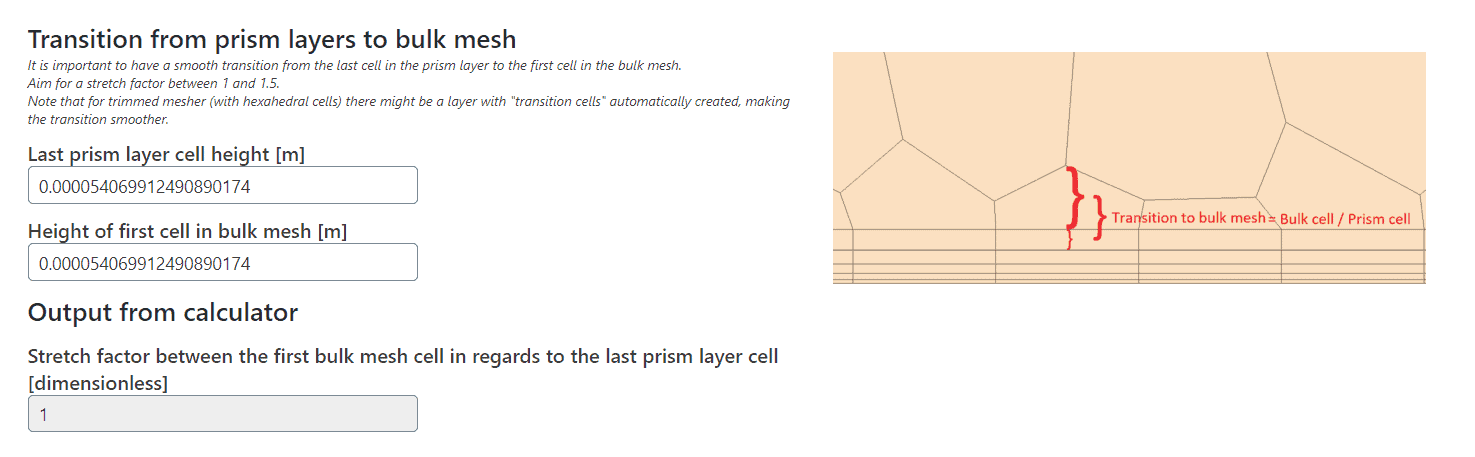
Transition from prism layer to bulk mesh – To get a good transition, from the prism layer mesh to the bulk mesh (mesh in the free stream), part 4 compares the last prism layer cell height (automatically updated from part 3 in the calculator) to the first cell in the bulk mesh. This train of thought can be used both for polyhedral and trimmed (hexahedral cells) meshers, but since trimmed cells are always growing by a ratio of 2 (becomes twice as large in a dimensions), there might be a “transition cell layer” of cells automatically added between the prism layer mesh and bulk mesh. This layer of cells, is difficult to predict (since it depends on where the bulk mesh cells are located relative the geometry), but will only help making the transition smoother.
The illustration to the right in the picture below visualizes how the transition from a boundary prism layer mesh of polyhedral cells to a bulk mesh could look like, and how the ratio in the output is defined.
How to use Volupe’s y+ calculator
Part 1 of this y+ calculator, defining the first cell height in the prism layer, is the common functionality of a general y+ calculator. The usage is therefore straightforward, changing between internal and external flow with the one-choice-button-field, and the possibility to customize the calculation by changing the value for parameters either by typing a value or using the arrows to increase/decrease the value.
Part 2 gives you a value of the boundary layer thickness, which is useful to know when choosing prism layer total thickness in part 3.
By changing the parameters in part 3, you can aim to obtain the value of prism layer total thickness, so that it corresponds to the boundary layer thickness from part 2. The first cell height is editable, but since the value is taken from part 1 it is not suggested to change this parameter, if you are not using part 3 independently from the outer parts of the y+ calculator of course.
In part 4 you can make sure the prism layer mesh will have a smooth transition to the rest of the mesh. The height of the last prism layer cell should be fairly similar to the first cell height in the bulk mesh, so that the change in size is not too large. By setting the base size of your mesh to the same value as the last prism layer cell height, you will obtain a smooth transition. It can also be beneficial to set the value of the last prism layer cell height as surface target size in your simulation. If the surface mesh is of similar size as the first bulk mesh cell, the aspect ratio (ratio of the longer side divided by the shorter side of a mesh cell) will be low, which is wanted (in the best case scenario, the aspect ratio is 1.0). These last tips are easier to achieve if your are working with a polyhedral mesher, but if you are using a trimmed mesher you should aim to always work in multiples of your base size to make the cells getting a smooth transition. A multiple can be 4, 2, 1, 1/2, 1/4, … which would correspond to 400%, 200%, 100%, 50%, 25%, … and should be applied on target and minimum surface size as well. If you have a complex geometry it might be difficult to create this smooth transition with trimmed cells, then you might save some time using polyhedral cells instead.
That was all for this week, we at Volupe wish you all happy meshing and a happy Easter holiday! If you need some help with your simulations, you are always welcome to contact us at support@volupe.com.
P.S. We know that this seems too good to be true, but the y+ calculator is real, not an April fool’s prank!