Today, the vast majority of the mechanical systems found in industries such as, robotics, automotive and industrial machinery, are all made up of several moving and interconnected parts. To study the motion and manage the accompanying complexity of these parts when designing, optimizing and controlling these mechanical systems, engineers often to rely on an engineering approach called Multi Body Dynamics simulation (MBD).
To study the motion and interaction of interconnected bodies subjected to external forces and kinematic constraints, Simcenter Amesim offers several mechanical libraries. In this article, we will have a closer look at how the 3D Mechanical Library accomplishes this.
The 3D Mechanical library allows you to model and capture the kinematics and dynamic behavior of three dimensional mechanical multibody systems. Simcenter Amesim provides you with libraries and components for modelling and simulating 3D mechanical systems. You assemble those components in Sketch Mode, and a 3D representation of the system is built for you. You can use the 3D visualization of your model to review the simulation results, animate, and to explore your system.

The models that you create with the 3D Mechanical Library can also be connected to other physical domains and controllers, all within a single simulation environment. (For example, landing gears with hydraulic actuation). You can investigate integration issues between your mechanical system and hydraulic system and components, electrical actuation systems, thermal systems, and see how it performs together with your control strategy.
Among the 3D Mechanical library’s components, there are several possibilities to compute geometric constraints in junctions (Lagrange equations, mechanical spring and damper, recursive joint).

The Lagrangian approach is likely the most common way of building 3D mechanisms in Simcenter Amesim. To resolve Lagrange equations, the Lagrange-Baumgarte stabilization method is used to set the Lagrangian multipliers. This approach introduces several implicit states to the mechanical solution, which excludes the export of real-time compliant models but offers significant speedup when it comes to computational time.
The mechanical approach makes use of springs and dampers to geometrically constrain two bodies based on the joint definition. This approach uses explicit states in its formulation and therefore introduces several vibration modes resulting from the level of stiffness and damping used in the joint. The method introduces no implicit states and is therefore real time compatible, however vibration modes can slow down the CPU time of the simulation. It is however possible to reduce the level of stiffness and/or damping within a joint to improve the simulation time, however when doing so the geometric constraint of the joint becomes less respected by the solver and may lead to erroneous behavior as a result.
The final method for defining geometric constraints is the recursive approach. This method is an interconnected tree approach where each junction depends on the previous junction (mother joint), and where each junction can have several daughter joints. This approach adds no implicit state to the solution and does not suffer from any potential un-respected constraints, as of the mechanical approach. The method can be particularly efficient in regard to simulation time if a model is constructed so that the first joint (trunk) is connected to a fixed and non-moving reference point.
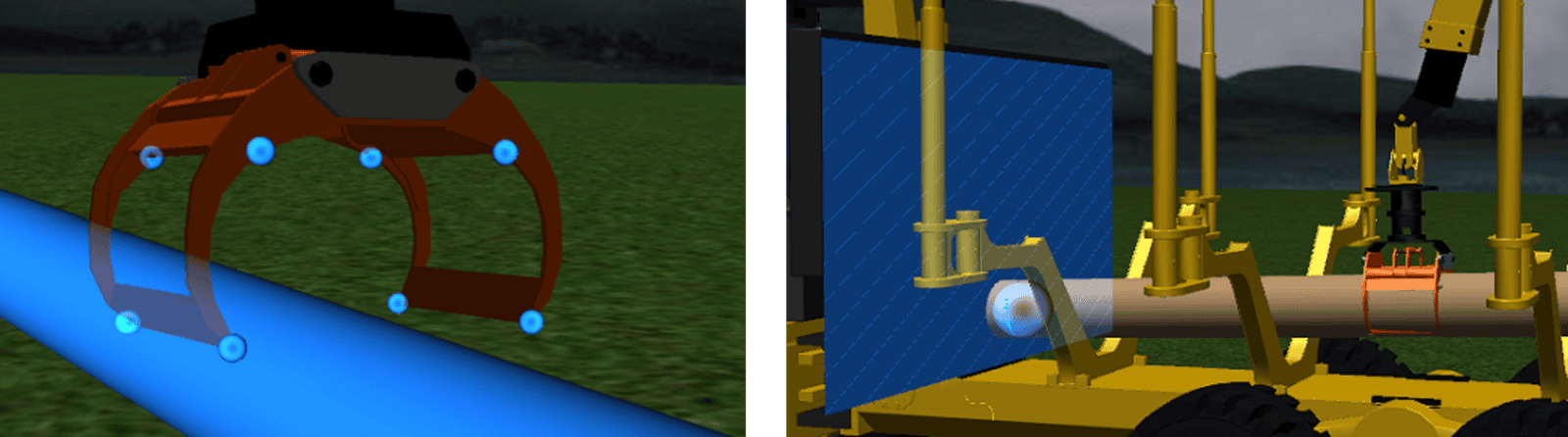
In the following example a mechanical system of a forest forwarder is shown. With this type of simulation model the dynamic motion of the crane can be studied, along with the accompanying instantaneous forces. This approach allows for the connection to a hydraulic system which in turn answers questions surrounding which hydraulic pressures are required to move the pistons controlling the motion of the arm (shown in the plot in the video below). All within the same simulation platform.

As presented above, the mechanical arm is made up of several mechanical components that form a system of connected ridged bodies. Between each ridged body junctions are placed. These describe the geometrical constraints between parts and may behave in different ways depending on the use-case. In addition to defining the motion of the arm using bodies and joints, the interaction with other objects can be of interest. For the forest forwarder above this involves contacts between the arm’s clamp and the log that is picked up by the machine. To account for these effects and to define how the arm and its surroundings interact, special contacts can be added to a model. These contacts can be defined as privative shapes (spheres, cylinders, boxes) surrounding the geometry, and which constrain the geometry from moving in a particular direction depending on its position. The contacts can also interact with an imported mesh, e.g. defining the ground, or be set to act as a rotating wheel, to mimic the wheel to ground contact.
We hope you have found this article interesting. If you have any questions or comments, please feel free to reach out to us at support@volupe.com.
Author
Fabian Hasselby, M.sc.