
In today’s blogpost we will review the options available in Simcenter 3D and Simcenter Femap to create midsurfaces of solid part assemblies. As calculation resource capacity grows rapidly these days, more and more assemblies can be solid meshed using automatic tetrahedral meshers or other automatic solid meshers like the hex-dominant mesher in Simcenter 3D and Femap. However, for thin-walled geometries where effects from surface stress concentrations, such as fillets, are not of main interest there are great advantages in creating a shell representation of the assembly.
The thing with solid assemblies is that to get high fidelity results for parts under multiaxial load, and bending, several elements through the thickness of the parts are usually necessary for reasonable mesh convergence. This results in a clear trend where geometry modification can be kept to a minimum and where a mesh can be rapidly created of solid assemblies. At the same time these also become very inefficient and can be very resource demanding as the number of elements generated will drive requirements on both computational power as well as on RAM amount (not to mention the data generated during solution of the simulation which is to be postprocessed later on).
Shell assemblies relieve the simulation of the increased demands on hardware set by solid assemblies by reducing the number of nodes and (in general) the number of Gauss integration points per element. Additionally fewer elements are generally required to model the same geometry as the thickness is no longer resolved explicitly but is instead set as a thickness on the elements themselves. The price to be paid usually ends up in more complex setup of the simulation by first having to reduce solids to midsurfaces and then connect these via the surfaces, various 1D connections or contacts. This outlines the general attributes of a shell assembly: It is slightly more complex to set up, but will generate results faster and will generate less data to process compared to solid meshes. This is ideal for simulations where responses of an entire structure is more important than stress peaks in a single radius and when many load cases need to be investigated. So how can we create these shell assemblies? How are midsurfaces generated in Femap and SC3D?
Femap Midsurface Generation
All of Femap’s midsurface creation commands reside under
Geometry→Midsurface
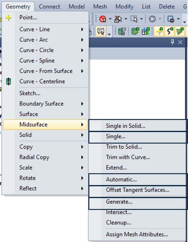
As seen in the image there are several options available to create a midsurface in Femap, but the Automatic command usually does the job well. It will generate a midsurface and we can enable options so that the output body is a trimmed, connected set of several midsurfaces from one single solid. Moreover, the Geometry→Midsurface→Assign Mesh Attributes command lets the user assign automatically created properties to the generated midsurfaces based on their corresponding solid representation’s thickness. Perfect to quickly setup models in a structured manner. Note that this only works for surfaces having constant thickness.
If geometries with more complex shapes are to be shell meshed Femap can also assign shell elements thicknesses and offsets on a per-element basis by using the command Modify→Update Elements→Midsurface Thickness and Offset
This will in the end modify nodal thicknesses on the CQUAD bulk data entry in the input deck for Simcenter Nastran.
Simcenter 3D Midsurface Generation
In SC3D you create the midsurface on the .prt level in the assembly using the Midsurface by Face Pairs.
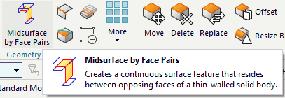
A convenient option is to do so in the idealized part. When doing so WAVE linking the solid body is the recommended option to enable the master geometry to be reworked and a midsurface to be created. The reason for not using Promote instead is that WAVE links are more robust in transferring attributes between the solid representation to the midsurface. These attributes are distinguishing SC3D from Femap in that geometry in that way can be made accessible to Selection Recipes to be used in semi-automised models where e.g. meshing algorithms or connections and contacts rely on attributes set in the assembly. Similarly to Femap, SC3D can utilise the midsurface definition to define element thicknesses. The perk in SC3D is the associative .fem which will update to geometry changes made to the solid representation of the midsurface. Updating the CAD model will also update the midsurface definition and the .fem file just needs to be Updated to automatically include the change.
Now if you have a more complex part to midsurface you can use the Manual Face Pairing selection in the Midsurface by Face Pairs to explicitly select which surfaces are to be used for midsurface creation. Moreover, you can specify additional surfaces to be used as replacement midsurfaces for even better control of the midsurface generation.
I hope you have gotten a good overview of the midsurfacing capabilities in both Femap and SC3D from this post. Be sure to send us an email on support@volupe.com with any questions you may have.
Viktor Hultgren, M.Sc.
Contact: support@volupe.com
+46 704 21 06 61