In this Simcenter Amesim post we will have a look at how design space exploration can be done on a system level together with the software Simcenter HEEDS. In a prior article (found here), we briefly discussed the field of optimization and looked into the capabilities of Simcenter Amesim. In this post we focus instead on providing a step-by-step example on how the software tools are connected and delve into the area of optimization using multiple objectives.
Simcenter HEEDS is a Multidisciplinary Design Optimization (MDO) software. The software package interfaces with commercial CAE tools to automate and improve the search for better products, provides insight through various analysis tools, and applies several optimization methods at once for a more efficient search.
In many engineering problems trade-offs are commonplace. In these, an attribute can usually only be improved at the cost of another. In such situations we would like to understand what the optimal trade-off is and know exactly how much an attribute can to be decreased and exactly how much is gained by doing so.
Optimization problems containing conflicting objectives are similar to the weighted sum approach discussed in (found here), but have the capability of managing multiple objectives independently of each other to generate a set of optimal solutions. This set of optimal solutions is called the Pareto optimal set. As the optimization algorithm performs its search of the design space, the members of this set are continuously updated and replaced with better solutions if found. As the optimization run progresses, the Pareto set continues to approach the ideal set of solutions called the Pareto frontier. In situations with more than two objectives this is no longer a front, but a surface or a set of solutions in a space of higher dimension. Pareto optimization selects its optimal designs based on whether they dominate other designs. A design is said to dominate another when it is better in at least one objective and not worse in all other objectives. Below in figure 1, an overview of what a completed optimization run with two objective funcitons could look like is presented.
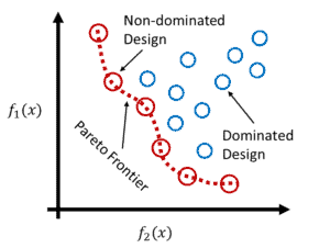
figure 1, an illustration of the concepts Pareto Frontier, Dominated and Non-dominated designs.
Setup in Simcenter Amesim
To showcase the process of setting up and running a multi-objective optimization using Simcenter Amesim and Simcenter HEEDS, a rudimentary driveline and vehicle model was used based on components from the IFP Drive library. A model overview and a few accompanying example plots are given in figure 2. The vehicle consists of a longitudinal vehicle model of a passenger car, a driver model set to follow the WLTC driving cycle, 1800 [s] long, and a generic control unit designed for series connected hybrid vehicles. The driveline comprises of a four cylinder, 1.8 [L], combustion engine connected in series with an electrical generator, a LFP battery, and an electrical motor. The battery was made up of a 100 cells connected in series.
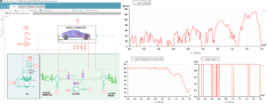
figure 2, overview of the vehicle and driveline model to be optimized. Plots of the WLTC drive cycle, battery State of Charge (SoC) and combustion engine activation as functions of time.
Vehicle propulsion is determined by the Vehicle Control Unit (VCU). The pre-built controller component VCU-SH receives information from the driver regarding acceleration and braking commands, rotary velocity from the electric motor and generator, and State of Charge (SoC) and voltage from the battery, as well as the vehicle speed from the vehicle model. The VCU then feeds load commands to the combustion engine, electrical generator and motor, as well as, when to start and stop the combustion engine. With this system layout the combustion engine can be used for both recharging the battery and supply power to the electrical motor directly. The engine is operated with the following modes:
- mode 0: the engine is stopped, the generator does not generate anything (torque command = 0),
- mode 10: the engine is starting, the generator use the battery to start the engine (torque command = maximum generator torque at port 16),
- mode 1: the engine is started, the generator is used to charge the battery and to drive the vehicle.
The VCU strategy contains several settings of which only three where varied in this study:
- requested power to start the hybrid mode: if this power or higher is requested, engine is started.
- requested power to stop the hybrid mode: if this power or lower is requested, engine is stopped.
- requested vehicle speed to start the engine: if vehicle speed is higher than this value, the engine is started.
To investigate the optimal trade-off between the combustion engine’s fuel consumption [g] and capacity of the battery [Ah], two objective functions were used. The total fuel consumption at the end of the WLTC cycle, and the battery model’s rated capacity of one cell was selected. The cell capacity was also used as an input variable in Simcenter HEEDS, together with the three VCU parameters.
Since not all simulations run until completion, e.g. due to a completely drained battery and no ICE activation, the simulation time was measured and passed on to HEEDS. This was then used as a constraint to ensure that successful solutions completed the entire cycle of 1800 [s]. Additionally, the maximum number of combustion engine restarts was limited in the optimization study to an arbitrary value of 20 starts for the entire run. This to avoid excessive cycling of the engine.
Setting which parameters Simcenter HEEDS will use is done through the Export Parameters Setup. This is opened either from parameter mode or simulation mode, and is found under the Interfaces menu and then Export Setup, as seen in figure 3 below.
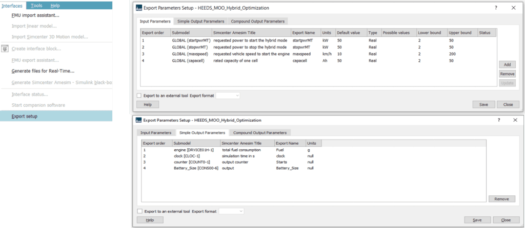
figure 3, Export Parameters Setup menu with intended model inputs placed under Input Parameters, and model outputs/responses placed under Simple Output Parameters.
The export parameters were added by dragging and dropping parameters and variables onto the export window. Care should be taken when defining the lower and upper limits of each parameter. If the study in Simcenter HEEDS passes parameter values outside this range, no updates will be done to the Simcenter Amesim model. Instead, values from the lower or upper bounds will be used to perform the simulation.
Since the Cell Capacity was used as both an objective function and an input parameter in this study, a simple Constant from the Signal & Control library was placed on the sketch. The purpose of this work-around was to pass on the Cell Capacity as an output in the Export Setup, and later use this as an objective function.
Finally, the model needed to be compiled and saved. Out of simplicity, the Simcenter Amesim model was saved in the same project folder as Simcenter HEEDS. Regarding compilation, no additional steps are required apart from making sure that the model actually has been compiled, e.g. by moving from Sketch mode to Simulation mode.
Setup in Simcenter HEEDS
In Simcenter HEEDS different processes and analysis blocks can be created and connected to automate a workflow or perform various studies. In our simple example we proceed by selecting the Simcenter Amesim portal under the analysis block to tell Simcenter HEEDS that we want to connect to Simcenter Amesim, see figure 4 below. Next, we navigate down to Files and then by right clicking select Add input file. Once the appropriate .ame file is loaded into Simcenter HEEDS we will be prompted with an option to Autotag variables. This is a convenient way to automatically create input and output variables from the parameters defined in the Export Setup in Simcenter Amesim and then automatically connect them. Note that if any changes have been made to the underlying Simcenter Amesim model after the model has been imported, it may be necessary to remove and add the .ame file again to resolve any errors messages that may show up when running the study. Additionally, the number of CPUs to run on can be set under the Execution tab.
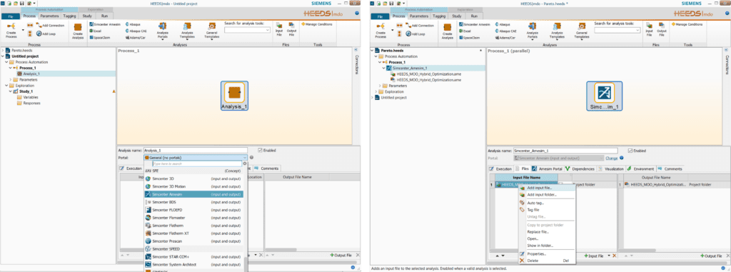
figure 4, Simcenter HEEDS Process view with selection of CAE portal and model to interface with.
Once Simcenter HEEDS and Simcenter Amesim has been connected and the variable tagging is done it is prudent to check the connection before we proceed with defining our multi-objective optimization study. A convenient way of doing this is to create a new Evaluation Only study and run and arbitrary design set. The results from this study could then be compared with the results from Simcenter Amesim using the same set.
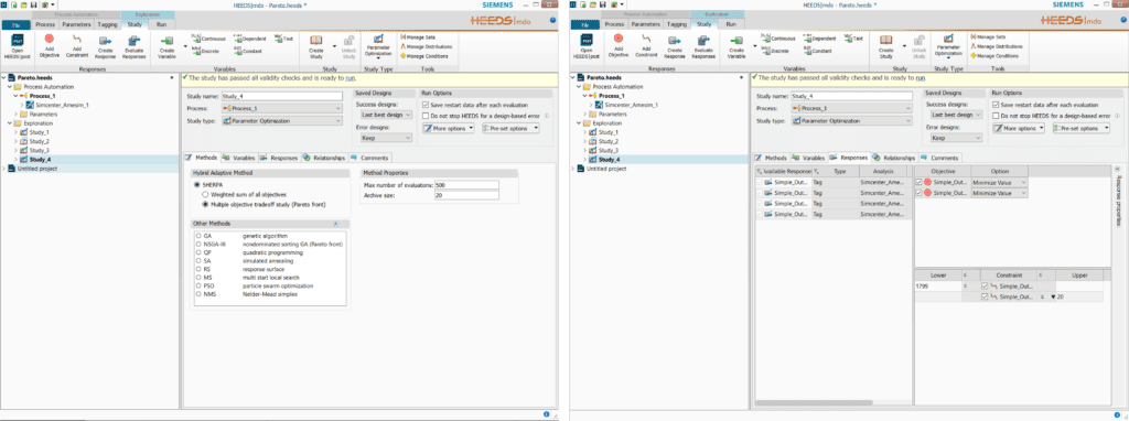
figure 5 left, Simcenter HEEDS Study view with a multi objective optimization study selected. figure 5, right, definition of variables, objectives and constraints.
As the goal with the study was to investigate the optimal trade-off between fuel consumption and battery capacity, the multiple objective optimization approach was selected to determine the pareto set, see figure 5. In regards to choice of optimization algorithm, few settings are required with the Simcenter HEEDS SHERPA methodology. The optimization algorithm, and accompanying settings, are automatically determined and updated throughout the optimization run to ensure as wide as possible search of the design space, and without impeding convergence time too significantly. If more direct control is desired the option to choose and set the algorithm yourself is still available.
Defining objective functions and constraints is done under the Responses tab, figure 5 to the right. The two response variables fuel consumption and battery capacity are added as objectives by dragging and dropping these onto the objective area. Constraints were set up using simulation time and number of engine restarts. Simulation time was constrained to be above or equal to 1799 [s] since the WLTC is 1800 [s] long. Engine restarts set to below or equal to 20 restarts.
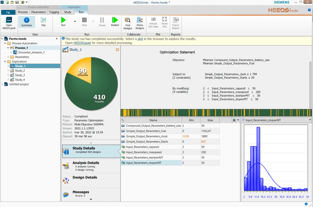
figure 6, Simcenter HEEDS Run view containing information regarding the problem statment, current progress, and potential error messages.
As seen in figure 6, the optimization statement is clarified and information concerning number of feasible and infeasible designs is presented. The study took 40 [min] to complete 500 evaluations on a laptop using 11 logic processers.
Although it is possible to work with plots directly in the run window, it is recommended to toggle the Open HEEDS Post button located in the run tab’s ribbon. By doing so more plotting options become available.
Moving on to the results. Below in figure 7, the optimal trade-off, i.e. the Pareto optimal set, is given in red using 20 points and blue points show all feasible designs. On the y-axis, total fuel consumption [g], and on the x-axis, battery size [Ah].
The number of points to include for the Pareto optimal set can be increased in the run setup in order to improve the resolution if desired.

figure 7, the optimal trade-off shown with 20 points in red accompanied by all feasible designs in blue.
Simcenter HEEDS provides many ways of analyzing results, such as determining patterns, finding similar designs, or investigating how sensitive a response is due to changes in input variables. One way of visualizing results is by using a parallel plot containing all input variables, objectives, and constraints. In figure 8 below, the Pareto optimal set’s 20 designs are shown in a parallel plot.
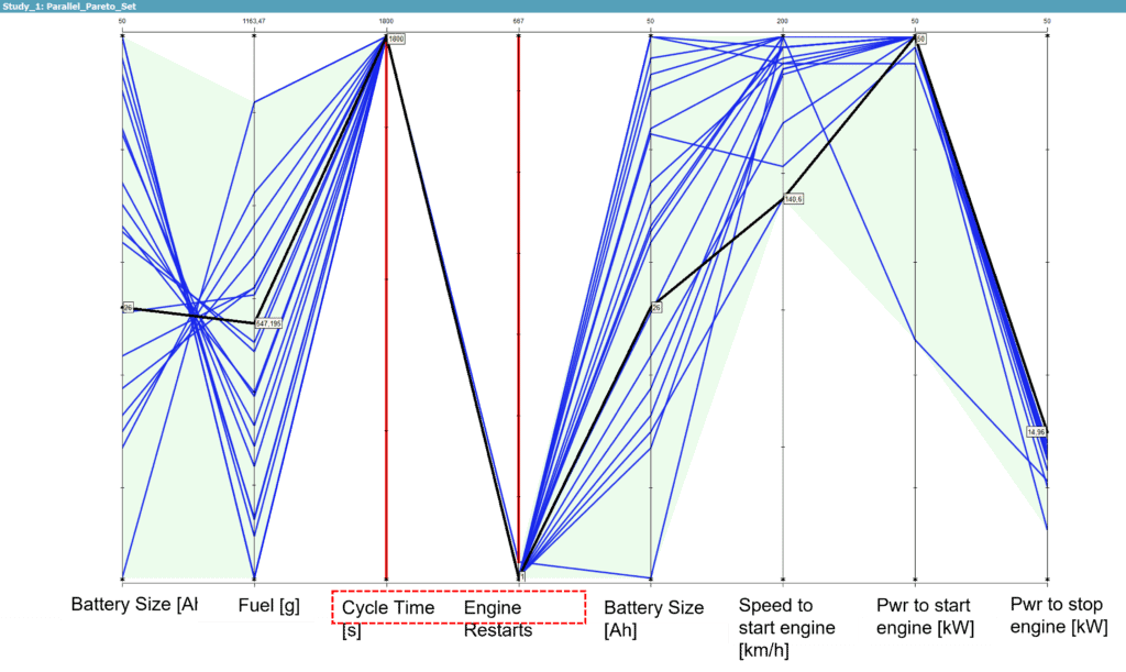
figure 8, Parallel plot of the objective functions to the left, the two constraints, highlighted in red, and input variables to the right.
Studying the values of the input variables in figure 8, rather unsurprisingly the preferred engine setting is to operate the engine sparingly. The engine is only activated at speeds higher than 140 [km/h], and preferably only when high power levels are requested. All designs tend to favor stopping the engine at lower power requests, i.e. keeping the engine active for a longer period of time. The later behavior is likely due to the constraint of number of engine restarts allowed.
The findings from this optimization study has limited real-world applicability. Hopefully instead, the approach offers some inspiration and guidance when setting up your own optimization study. Typically, more parameters and constraints are required to form a proper problem definition, as well as in this case using several longer driving cycles. Aspects like battery aging could be introduced as an additional third objective function to capture the influence of repeatedly recharging/discharging on battery degradation.
We hope you have found this article interesting. If you have any questions or comments, please feel free to reach out to us on support@volupe.com
Author
Fabian Hasselby, M.sc.
+46733661021
