Marine maneuvering simulations in STAR-CCM+ can be approached in two fundamentally different ways. The Moving Forced Wave Tank (MFWT) with overset mesh is the go-to for complex wave environments and large excursions. But for moderate-motion cases, especially calm-water or mild-wave maneuvering, DFBI mesh morphing in a single domain offers a cleaner, overset-free alternative. This post walks through the complete morphing setup, including how to superpose a time-varying rudder rotation on top of the ship’s six-degree-of-freedom motion.
Two approaches to maneuvering simulation
The Moving Forced Wave Tank approach
The conventional setup for ship maneuvering in STAR-CCM+ pairs DFBI Rotation and Translation motion on an overset region with a background domain that uses DFBI Follow Motion. This approach is outlined and recommended procedure by Siemens, known as the Moving Forced Wave Tank (MFWT) concept. The overset background domain follows the ship’s horizontal displacement and yaw (3DoF), while the vessel itself is free to respond to all six degrees of freedom. Wave boundary conditions are prescribed at the tank edges using the forcing method, keeping reflection artifacts out of the domain regardless of how far the ship travels.
This combination is powerful and general. It handles large drift angles, arbitrary heading changes, and wave environments without any mesh quality degradation over time. The tradeoff is setup complexity: overset interpolation introduces an additional source of numerical error at the donor–acceptor interface, and careful attention to cell size ratios across the overset boundary is required to maintain accuracy.
DFBI Morphing: the single-domain alternative
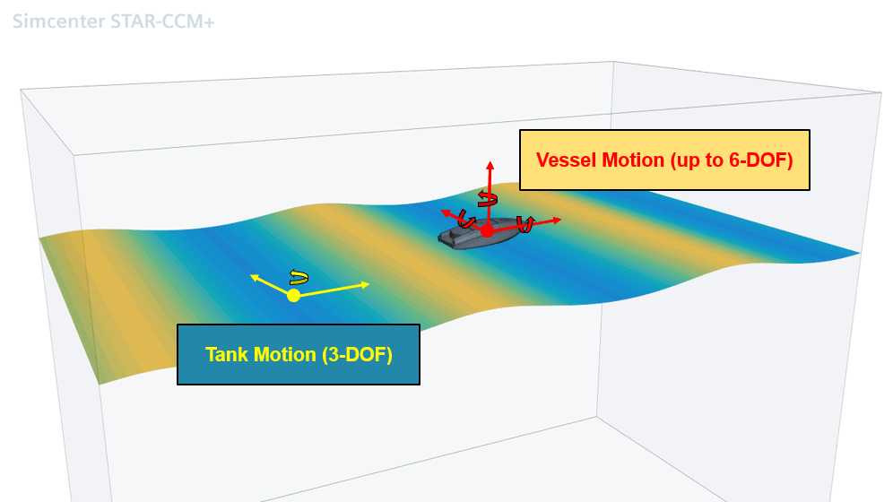
DFBI (Dynamic Fluid Body Interaction) Morphing addresses this by keeping everything in a single domain. The movement of the 6-DOF body is introduced by displacing mesh vertices relative to region boundaries. However, to account for the tank movement, the outer domain moves rigidly in a limited number of degrees of freedom to keep the ship roughly centered: typically surge, sway, and yaw. This is conceptually identical to the Follow Motion used in the MFWT approach.
Because the outer boundaries follow the ship’s gross motion, the computational domain stays small, just like the MFWT tank, and the free surface refinement zone remains correctly aligned at all times. Because the morpher only has to accommodate small residual motions, mesh quality is well preserved even for extended maneuvers. And because everything is a single connected domain, there is no overset donor-acceptor interpolation step.
Setting up the morphing domain
The starting point is a standard self-propulsion or resistance simulation with DFBI Rotation and Translation assigned to the hull region. The first step is to change the motion model on the hull region to DFBI Morphing. This is a region-level change; nothing else in the simulation tree needs to change at this stage.
Outer domain boundaries
Select all fluid-domain boundaries that have no direct connection to the DFBI hull body: the inlet, outlet, bottom, top, and side faces of the domain. These boundaries must move rigidly with the ship’s gross motion (surge, sway, and yaw) to keep the domain centered around the vessel throughout the maneuver.
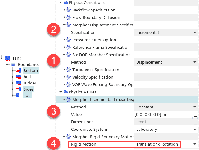
In practice this is done by setting the Six DOF Morpher Specification on these boundaries to “Displacement” with constant linear displacement of zero. The movement comes from the Morpher Ridged Boundary Motion instead (4 in the figure above), which is set to a reading the 6-DOF reports of x and y-translation and orientation (heading angle):
Alternative setup: Planar Motion Mechanism (PMM)
An alternative to 6DOF free motion, driven by propeller force, can be prescribed maneuver motion with the Plana Motion Mechanism. Here we have possibility to prescribe the planar translation as well as yaw.
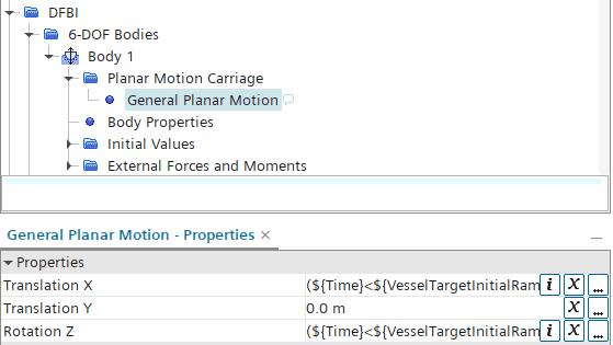
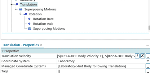
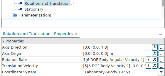
Similar to a free motion case, we can determine the rigid motion of the outer domain from the 6-DOF Body report to define the Morpher Rigid Boundary Motion as a superposed motion or directly as Rotation and Translation motion.
Hull surface and internal interfaces
Select all remaining wall boundaries, the hull surface, appendages, and any internal boundaries which are port of the DFBI Body and set Six DOF Morpher Specification to Six Dof Body.

These boundaries will now deform with the DFBI body at every time step, with the morpher smoothly propagating the displacement field from the body surface out to the fixed far-field boundaries.
An example: hinged body in a flow
Taking a simple example of a hinged body subjected to an inflow stream (with the computational domain fixed), the body is free to rotate around the upper-left corner. From the video below, we can observe how the body rotates while the mesh follows the motion.
Initially, the mesh morphing is limited by the distortion of the cells. However, the remeshing model can be enabled to monitor cell quality and automatically trigger a remeshing operation when needed.
After each remeshing step, it is important to ensure that, whenever the mesh pipeline accesses geometry surfaces, the surface positions are synchronized with the positions of the region boundaries. To achieve this synchronization, consider the following preferred approaches:
- Modify the parameters directly in the 3D-CAD model according to the morpher displacement, so that the resulting geometry surfaces match the boundary positions.
- Apply the same predefined motion to the geometry under Geometry > Operations > Transform > Transforms > Motion
Since the motion is not prescribed explicitly, but instead develops naturally from the fluid forces, a Motion Transform operation using “Body 1 Motion” can be applied.
Adding superposed rudder motion
With the hull region assigned to DFBI Morphing and the propulsion system resolved (using a virtual disk and Planar Motion Mechanism), the final step toward a complete manoeuvring simulation is the implementation of rudder deflection.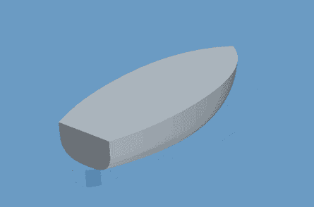
The rudder rotates relative to the hull, while the hull itself is free to move in all six degrees of freedom. This requires a superposed motion: a rotational motion whose axis and centre of rotation are defined in the DFBI body coordinate system rather than in the global laboratory frame.
Creating the superposed rotation
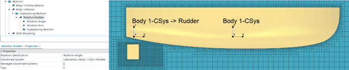
In the motion tree, the DFBI body already contains an associated motion specification. Under this specification, create a new Superposed Rotation Motion for the rudder. The rotation axis should pass through the rudder stock location and be defined in the DFBI body coordinate system. By doing so, the rotation axis automatically follows the ship motion during the simulation.
Rudder region setup
The rudder and hull remain within the same mesh region, but Per-Part Meshing must be enabled. As a consequence, the rudder boundary must be assigned a rigid motion corresponding to the superposed rotation.
The setup consists of two components:
- Set the Six DOF Morpher Specification to Six DOF Body. This ensures that the rudder deforms consistently with the DFBI body and follows the ship’s surge, sway, heave, roll, pitch, and yaw motions.
- Apply the additional rudder rotation through Morpher Rigid Boundary Motion.
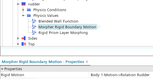
The morpher will then rotate all rudder surface nodes about the rudder stock axis while simultaneously propagating the DFBI body displacement.
Driving the rudder angle
The rotation angle of the superposed motion can be controlled through a field function, allowing predefined maneuver profiles such as sine sweeps or Z-maneuvers.
A practical implementation is to use a table interpolation based on simulation time.
Remeshing with superposed motion
The standard Remeshing model used in the hinged DFBI body example cannot be applied directly in this case. The reason is that the remeshing transfer operation does not support superposed motions.
Instead, the workflow must rely on the Morph Surface Mesh operation. This operation allows explicit surface displacement independent of the prescribed motion framework.
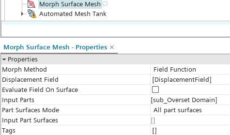
Here, the displacement field is defined as:
$${Position} – $${SavedCoord}
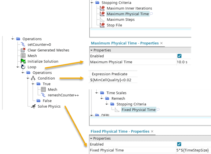
The limitation of the standard Remeshing model is that it cannot correctly preserve the relationship between the rudder rotation coordinate system and the Body 1-CSys when superposed motion is present. However, the same behavior can be reproduced using Simulation Operations.
The simulation is executed in a loop until a global stopping criterion is reached (for example, a fixed simulation time of 10 seconds). Within the loop, the mesh quality is checked periodically after a specified number of time steps.
If the mesh quality falls below a defined threshold, a remeshing step is triggered using the Morph Surface Mesh operation.
Summary
DFBI Morphing offers a practical single-domain path to manoeuvring simulation that avoids the complexity of the overset interface while retaining the key advantage of the MFWT approach: a small, ship-centred domain that travels with the vessel. By letting the outer boundaries move rigidly in surge, sway, and yaw and delegating only the residual heave, roll, and pitch to the morpher, mesh quality is well controlled even over extended manoeuvres.
The addition of superposed rudder motion demonstrates how the morphing framework can accommodate multiple, nested degrees of freedom within a single region. The one area requiring a custom solution is remeshing: because the built-in Remeshing model cannot preserve the relationship between the rudder’s rotation co-ordinate system and the DFBI Body coordinate system, the Morph Surface Mesh operation combined with a Simulation Operations loop provides an equivalent and fully controllable alternative.
For cases involving steep waves, large roll amplitudes, or slamming the overset-based MFWT remains the more robust choice. But for the broad class of calm-water and mild sea-state manoeuvring problems, DFBI Morphing provides a clean, accurate, and setup-efficient solution.
The Author
Florian Vesting, PhD
Contact: support@volupe.com
+46 768 51 23 46