In this week’s blog post we will introduce the Mesh Alignment feature of the Trimmed Cell Mesher in Simcenter STAR-CCM+, which could be good to have in your engineering toolbox.
Performing Mesh Alignment on a block
The default setting of the Trimmed Cell Mesher creates a mesh that is centered and aligned based on the global bounds of the geometry part. If we exemplify this using a simple block, it could look something like this:
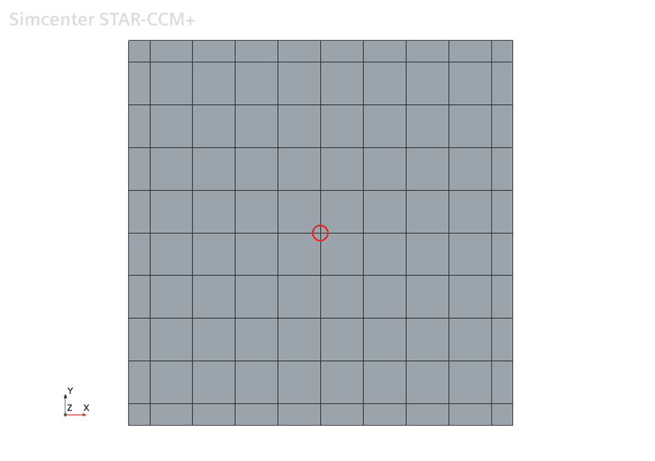
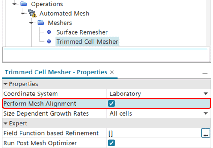
Here the default reference point for the mesh is highlighted with a red circle and as you can see it is automatically positioned in the geometrical center of the domain. Because of the dimensions of the block and the cell size used, this causes the boundary-adjacent cells to be cut in half. Knowing that the chosen cell size and the size of the block should allow for an isotropic cell size throughout, we can now make use of the mesh alignment setting to make that happen. We start by going into the Trimmed Cell Mesher properties and enable “Perform Mesh Alignment” (see below).
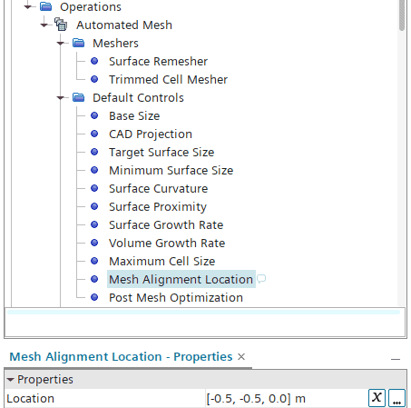
Once we tick this box, the Default Controls folder is populated with a node for Mesh Alignment Location. For this example we decide to put the reference point in a corner instead, in this case [-0.5, -0.5, 0.0] m as depicted below.
If we have a scene open, the new reference point (bottom left corner) is highlighted with a small magenta-colored sphere, as shown in the picture below.

Now that we’ve set the new reference point, we can execute the mesh again to obtain the following mesh instead:
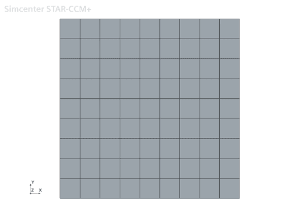
Now we have successfully used the mesh alignment setting to obtain an isotropic cell size throughout the block.
Aligning interfaces for coincident parts
The mesh alignment feature can also be used for aligning interfaces when you’re using the Trimmed Cell Mesher for coincident parts. As discussed in a previous article (https://volupe.com/simcenter-star-ccm/contact-mode-interfaces-in-simcenter-star-ccm/), only the tetrahedral or polyhedral meshers are able to generate conformal interfaces out of the box. This is due to the current implementation of the Trimmed Cell Mesher, which does not allow for several parts in the same operation. In order to override this limitation, you need to use the “Per-Part Meshing” option for the Mesh operation, but using this setting cancels out the creation of conformality. However, in some cases you can utilize the mesh alignment to overcome this limitation. The example below will show exactly how.
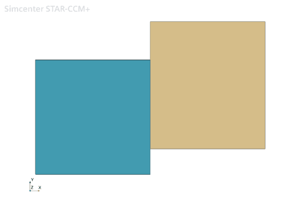
Let’s consider an additional block that is coincident with the previous block, only slightly offset in the y-direction.
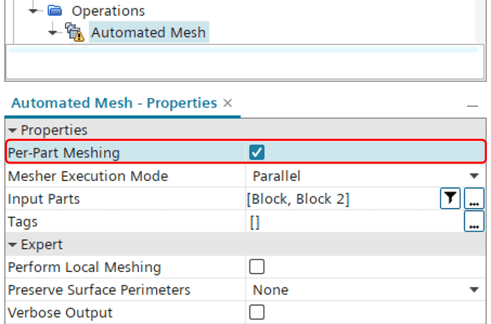
We decide to mesh the blocks using a single Trimmed Cell Mesher operation, but in order to do so we need to check the box for “Per-Part Meshing” (as depicted below). If not, we would get a warning about self-intersections.
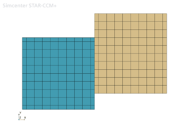
Running the mesh with default settings, we would end up with a mesh like below. As you can see, there is a misalignment between the cell vertices along the interface, since the Trimmed Cell Mesher puts the reference point in the geometric center of each part. This is where the mesh alignment comes into play again.
So, let’s see if we can improve the node matching along the interface. We move back into the Mesh operation, and once again we tick the box for “Perform Mesh Alignment”. We use the same Mesh Alignment Location as before (bottom left corner), and re-mesh. Now we end up with the following result:

As you can see, in this particular example we managed to get a perfect alignment of the cell vertices. This may of course not always be the case, but in many cases you could likely improve the match using mesh alignment.
I hope you found this feature useful. As always, feel free to reach out to us at support@volupe.com.
Author

Johan Bernander, M.Sc.