In this week’s blog post we will take a closer look at mesh-morphing. In many situations it is necessary to include motion of one (or several) object in your simulation. Usually this is done by applying an interface between the rotating and static region, either using sliding mesh or an overset approach. There is another option to this, and that is to use morphing instead. When we morph, we let an object move and the surrounding volume mesh distort (morph) according to the motion. This post is here to understand how to use morphing and what tools we can combine with the morphing workflow to improve our results. We will specifically look at point sets and how we can use those to decide where the bulk of the distorted cells end up.
If your object is changing shape during the simulation, morphing is the only feature will solve this for you, therefore it can be a handy tool to have in your toolbox.
How to setup a morphing motion
As an example, we will try to replicate the fin-motion of a shark swimming in water. This shark is named Bruce. Granted this is not an exact replica of what happens in nature, but you get the idea.
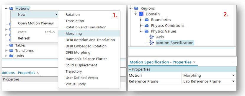
How do we get this type of morphing to happen in Simcenter STAR-CCM+? First you need to make sure that you are doing a transient simulation. The necessary selections and options are available when you have selected a transient simulation in your physics continua. The second thing to create is the necessary motion under “motions” in tools.
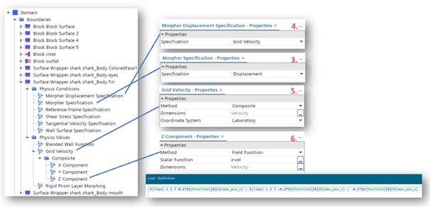
The picture below shows the steps. (1.) Create the morphing motion, you do not apply any specific selections for the created motion, more than the type of interpolation you want. (2.) Apply the morphing to the region where there are objects/surfaces that should morph. We specify the motion on the object we want to prescribe a motion to, in this case it is the shark’s fin. (3.) The default setting for morpher specification is “fixed”, meaning that the surfaces will not morph until you specify this. Here, we select the surface related to the tail fin and start by changing the morpher specification to displacement. (4.) We then select the type of displacement we want, here a grid velocity. (5.) After that we select composite for the grid velocity as we want to specify motion only in the z-direction, and that is the easiest way to separate the coordinates. (6.) We then select a field function as input for the z-velocity. (You can see the expression used in this example in the picture.)
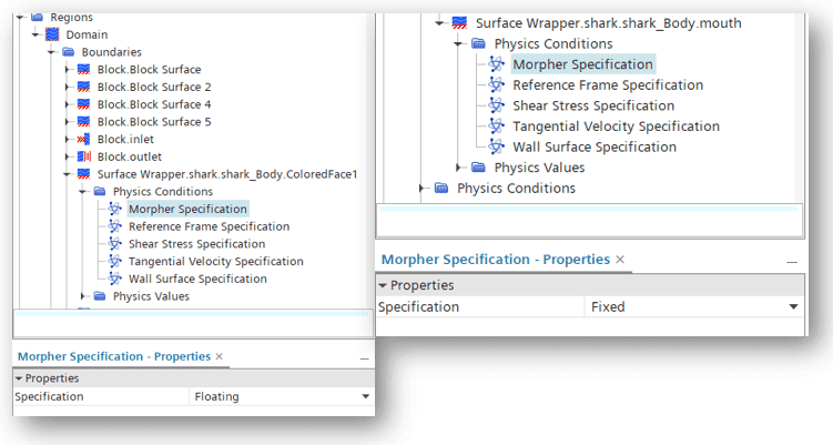
We have now set the motion for the fin, but for all the other surfaces to not become completely distorted in the first timestep, they need “flexibility”. This is done by specifying the bulk of the shark’s boundaries as “floating”. The only “fixed” object we keep is the shark’s mouth and eyes. Meaning that they will not follow any motion happening anywhere else on the shark’s body, and the floating boundaries between the fixed and morphing objects will move with those two constraints in mind.
How to avoid distortion in specific locations?
As we saw in the video of Bruce, the mesh distortion can become quite substantial. If the motion you have is small in relation to the mesh around it, the distortion is limited by the fact that no individual cell needs to change by a large amount. We are rarely in this situation however, and motions can be large in relation to objects in the surrounding. This can of course be combined with the remeshing solver, where you create a new mesh around the object, or rather for the entire region associated with the motion. However, there are a few tools for the morpher we can utilize to at least in part impact where the cell distortion happens.
To look at this we will use a very simple example of a sphere moving in a pipe. Note, that this type of motion is more easily simulated with sliding mesh or with overset mesh, but we use it here anyway as an example. The top left picture uses the default settings for the morpher and you can see that neither prism layers nor the surrounding bulk mesh retains their initial mesh in any good way. In the top right corner, we apply the feature “Rigid prism layer morphing”, and we can see that the prism layer is maintained, even though the bulk mesh is distorted. This can be an important setting if the prism layer result plays a large importance in your simulation. The bottom left picture utilizes something called a “point set” (more on how to create that below). This allows us to lock the bulk mesh inside our point set, making sure that we move the distortion of the bulk cells to outside our point set. The bottom right corner uses the rigid prism, the point set and remesh for reference. You decide in your certain situation what method to use for the best result.
Creating a point set
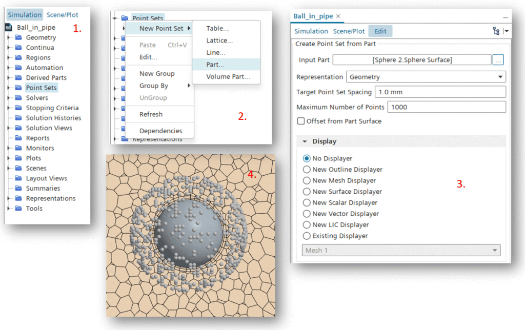
We can create a point set as soon as there is a morphing motion defined, and that morphing motion has been selected under motions for any of our regions (1.). (2.) In our example we want to force the morphing of the bulk cells to move as if the sphere was translated. This is done by using a shape part of a larger sphere. (3.) We set the representation to Geometry (as it is a part we are using as input) and a target spacing between the points, we then also define the maximum number of point we wish to use. If our conditions do not align (e.g., the spacing demands more than the maximum number of particles) the particles will be applied randomly on the geometry surface. (4.)
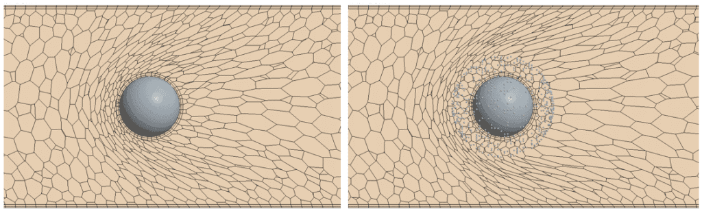
In a simulation like the example we are using, where the morphing happens based on a constant velocity of the sphere, the point set needs to match the velocity in order to maintain the bulk cells around the sphere. It also needs the motion specification of morphing assigned to it. However, while the morpher displacement specification for the sphere is set to grid velocity, we need to set the point set morpher displacement specification to either total, incremental or target position. We use an incremental specification here to match the timestep size and the grid velocity of the sphere. A closer look at the result with and without using a point set is found in the picture below.
I hope this post has given some ideas of what is possible when it comes to morphing together with using the features that are associated with morphing. The point sets are really useful if you have strict requirements for the mesh in certain regions. It can also be placed in far-field locations assuming you have features where you are very careful with the mesh in those locations. For any questions, reach out to support@volupe.com.
Author

Robin Victor
+46731473121
support@volupe.com