Fluid Mixing in Simcenter Flomaster

Fabian HasselbySenior Application Specialist
In short
Multi Fluid Simulation in Simcenter Flomaster mixes similar fluids, liquid with liquid or gas with gas, into a homogeneous mixture whose density, viscosity and other properties follow from the concentrations. Pipes delay concentration changes, and Fluid Modifiers add, remove or separate components, as in desalination.
In Simcenter Flomaster it is possible to account for varying fluid concentration in a system due to mixing. Streams having different fluid composition can be mixed to form a new homogeneous mixture along the flow path, and where fluid properties, such as density, viscosity, and thermal conductivity, are derived from the concentration of each incoming fluid.
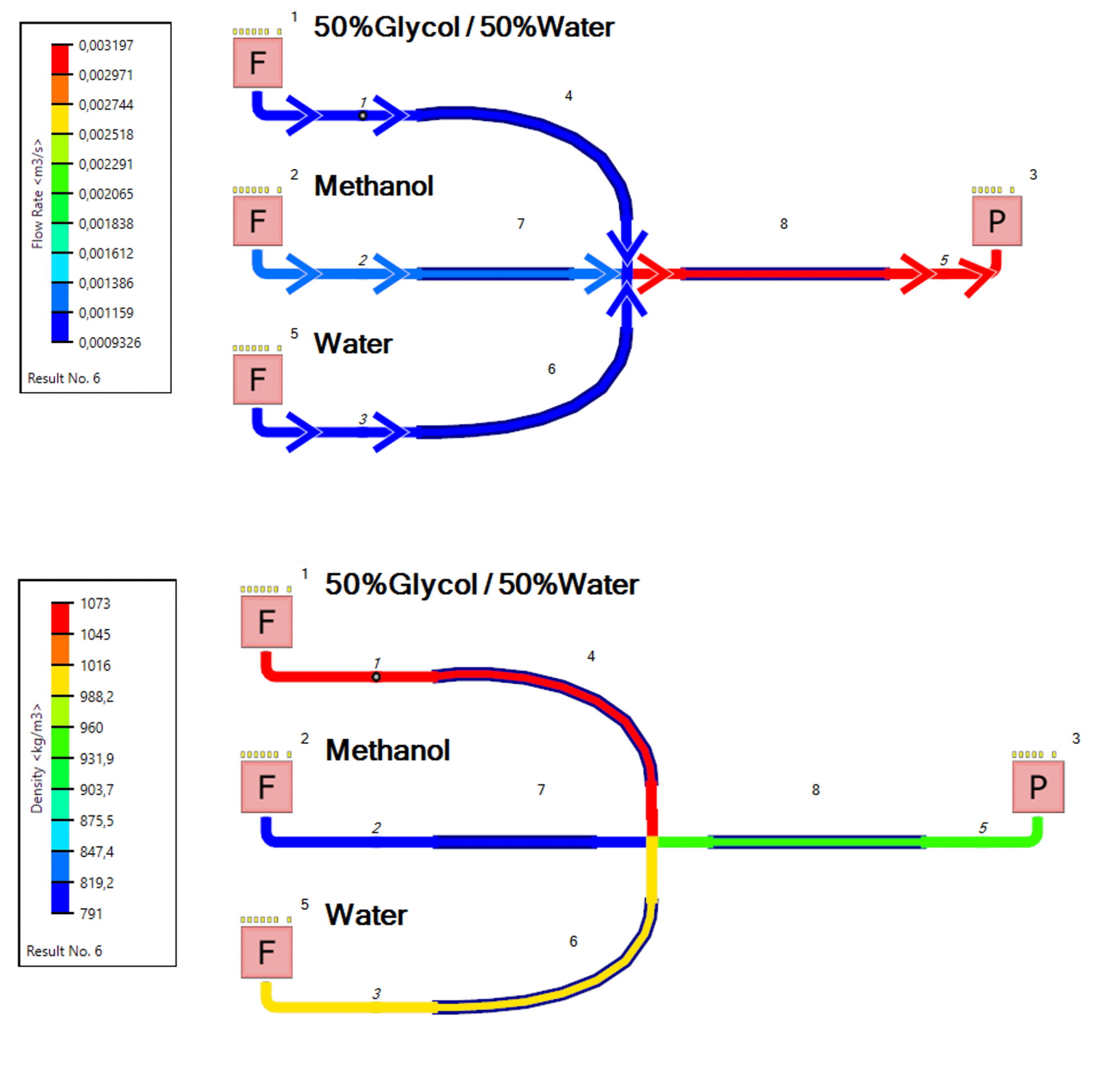
Three separate fluids mixing and resulting in a fluid mixture with a new aggregated density. The mass flow rate of each stream controls the final mixture concentration in the example above.
To enable this type of mixing throughout a system the simulation option “Multi Fluid Simulation” must be enabled before a simulation is run. This is configured under the tab “Simulation Data”, where you normally select which simulation to perform, such as steady-state, transient, or heat-transfer. Multi Fluid Simulation in Simcenter Flomaster takes a homogeneous modelling approach for computing fluid mixing, and the resulting fluid properties are evaluated based on the individual and known component properties and Dalton’s law. The approach allows for similar fluids to be mixed, such as liquid-liquid or gas-gas mixing, not the combination of these, water and air for example.

In the example shown in the first image of this blog, mixing takes place at the node between the pipe components. In this scenario no volume or residence mass is considered, and concentration does not accumulate within the node over time. To study such behavior components such as pipes, bends, junctions and transitions are used.
Within a fluid volume the resident mass may vary over time during a transient simulation, and the incoming concentration may be different from the outgoing concentration. As such, a change in concentration at a pipe inlet is not immediately propagated to the pipe outlet, which would be the case of a zero length component like a discrete loss. The reason for this is that the concentration information takes time to travel the full length of the pipe and will depend on factors such as bulk velocity.
The accumulation and concentration build-up within a volume can be described with the following expression for conservation of the jth fluid’s concentration.

Discretizing the conservation equation for the control volume yields the expression underneath, which can be arranged to solve for the outlet concentration during each timestep.
Fluid Modifiers.
To manipulate, remove or add fluid components, and modify concentrations leaving a component, Fluid Modifiers can be used. These components can be connected in the system to, for example, replace a fluid component with another during a chemical reaction, or to separate out parts of a mixture through a filter e.g. during desalination of sea water to fresh water and brine which is done in the simulation below.

Concentration of water shown in a system using a 3-armed Fluid Modifier.
Fluid Modifiers behave like simple loss components and by setting the loss coefficients and cross-sectional area pressure drop across the component is calculated. If it is desirable to modify the flow resistance further, or alter the pressure drop behavior in a certain way, other components such as discreate losses, or orifices, can be placed adjacent an outlet and thereby augment the pressure drop calculation.
Apart from modifying fluid concentrations exiting the component with constant ratios (set in the concentration sub form for each branch), the Fluid Modifiers can take this information as external signals from one or several controllers. This option allows users to create simple control logic to control output temperature and heat release, or add user defined scripts to calculate output concentrations as a function of input concentration, as shown in the image below.

Using the Controller Template component and setting the Algorithm Type to Script, is a convenient way to bring in coded behavior using C#, Java or VB. A benefit of this approach, compared to creating a new script-based component, is that most of the coding is done and users only need focus on defining the control. Information regarding the different types of built in functions, such as Controller.OutputConcentrationValue(), can be found under Help –> Simcenter Flomaster SDK Help (Software Development Kit)

We hope you have found this article interesting. If you have any questions or comments, please feel free to reach out to us at support@volupe.com
