The first release of year 2025 for Simcenter STAR-CCM+ is here, and this week’s blog post will cover some selected features for version 2502 when it comes to CAD and mesh handling. We will for example go into extra detail for the new feature of Virtual body, which will change the way of working with moving bodies for some applications, which previously needed overset mesh or morphing.
Before going into details about the handy features, it is a good idea to mention that
version 2502 of Simcenter STAR-CCM+ now requires Siemens license server
to handle your licensing. Siemens license server now uses the shared daemon “saltd” for all license types, compared to the previous license set up were each software had its own daemon, Simcenter STAR-CCM+ employed “cdlmd” for example. The default communication port is now 29000, instead of 1999, which needs to be open for communication between server and client. Siemens license server will modify your license file for you in the installation and store the license as a .lic file in a folder for Active licenses (so that the daemon and port will be correct, corresponding to the settings in the installation).
We recommend uninstalling the previous version of the license server before starting the installation of Simcenter STAR-CCM+ version 2502 (this version of the software includes the installation of Siemens license server),
so you can follow the installation procedure with standard settings. If your license is handled on a server machine, please configure this machine first. For those of you who use Volupe service for handling your licenses, all servers are already updated.
Virtual body
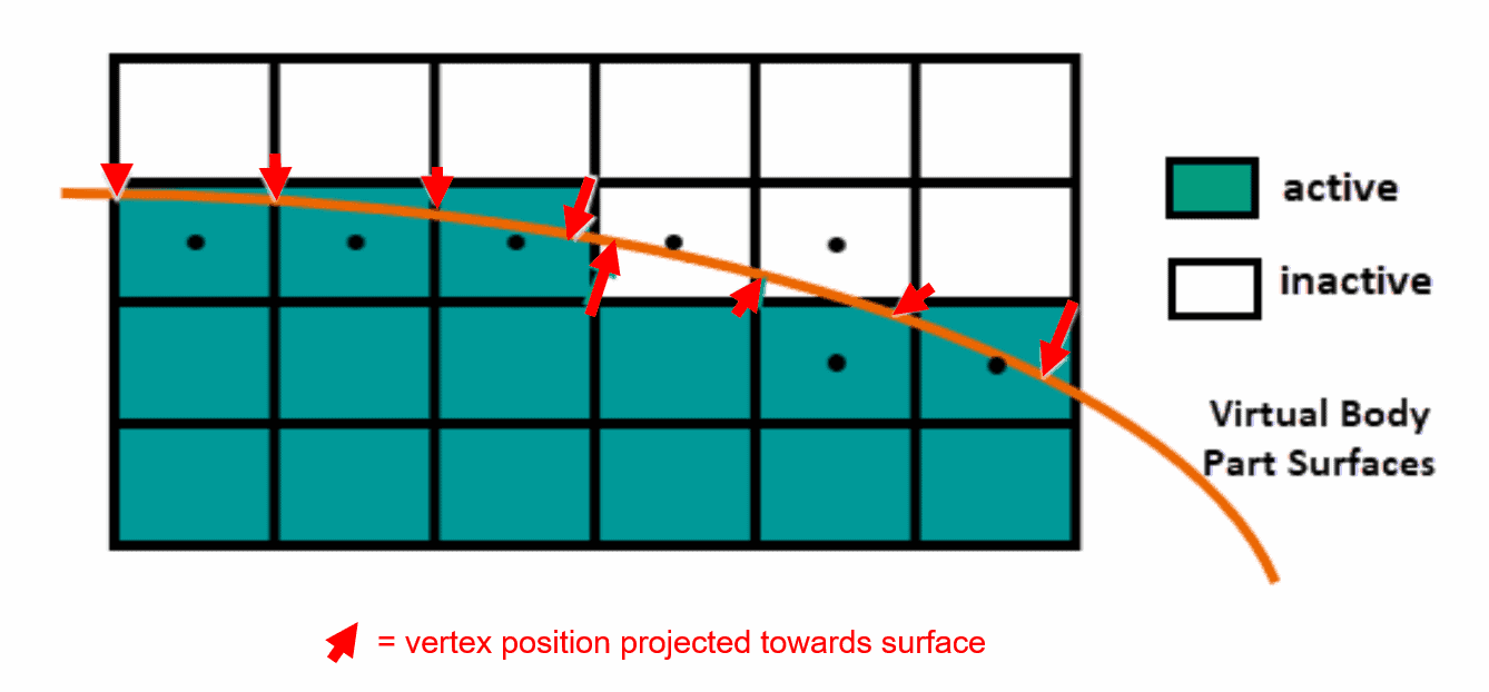
Now, moving to the new features of Simcenter STAR-CCM+ 2502, and looking at a new strategy for moving bodies – Virtual body. Virtual body is definitely one of the major news for this release, where this new feature can be used instead of overset mesh or movements using mesh morphing. This strategy uses the Immersed boundary method. Using Immersed boundary method gives the benefit of treating geometry information after the mesh is created, and if the body moves the information about where the wall/interface is located is updated in the cell. Since there is no interface between the body and background mesh, the background mesh instead uses geometry surface information to set cells to be either on the fluid or moving body side. In the picture below you see which cells are active or inactive (containing or not containing fluid field variable information) based on the virtual body surface.
Virtual body is a model that you activate in the continua. When the Virtual body model is activated, you can add a Motion in Tools that is called Virtual body. When this motion is activated within a region you can create new boundaries of type Virtual body boundary. Using the wanted part as input part to a Virtual body boundary will cut a hole in the mesh and inactivate cells that no longer is part of the fluid domain. To move this virtual body the virtual body motion can be set to use a specific motion (for example translation) that you have created as well, in the Motions in Tools.
Some guidelines on how to use Virtual bodies are good to mention since at the moment this feature is working best for simulations like in the picture below (filling up containers with a VOF phase). AMR is compatible with Virtual body, but prism layers cannot yet be formed on the virtual surface. Trimmed (hexahedral) cells are to be preferred together with this model, especially if AMR is used. Close gaps are well handled since the model has a method to recognize narrow gaps and thin objects, where extended projection from cell vertices is used so there will be no hole in the geometry even though thin gaps are present. Not only is virtual body easier to set up and require less settings, but it is also a faster method than overset mesh.
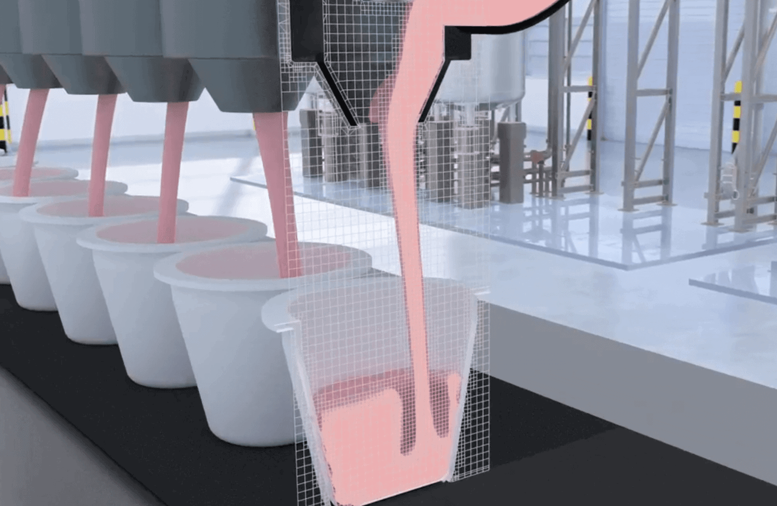
To clarify, there is no mesh in the cup since it is a virtual body. The boundaries for the virtual body are specified in the region and is referenced to a geometry part. When the cup starts to move (due to the motion specified for the boundary) the cell information is updated and cells are changed to inactive if they are inside the cup and activated if they go from being in the cup to in the fluid domain.
Below you find a video on how the virtual body model will look like when implemented for this VOF simulation.
Wake refinements (improvements and periodic compatability)
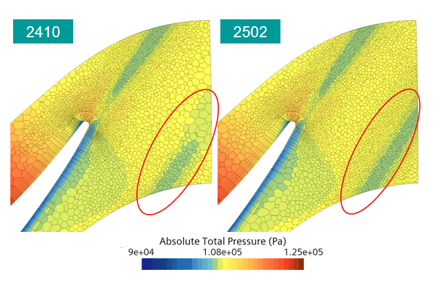
Wake refinements are set up as surface refinements in the automated mesh operation. Using wake refinements instead of volumetric refinements based on specified volumes will save time creating dummy volumes and make sure that fine cells are spent where they need to be. The flexibility of defining spread angle and distance makes this feature useful in a lot of simulations. In version 2502 the wake refinements can continue through a periodic surface as well, and this is for all mesh types. See picture below for a comparison against previous version, 2410. In the top of the picture fine cells are used in the wake but this setting is not transferred to the bottom part of the picture through the periodic boundary in version 2410. Additionally, the wake refinement is generated faster in the new version (almost up to 50% faster in specific cases) and less cells are used because the algorithm spreads the cells in a smarter way. So, if you are not already using wake refinement, instead of volumetric refinements, the time to start using them is now.
Surface repair selection using bounding shapes
There have also been updates for Surface repair, where one of the most useful ones is making it easier to select surfaces. Bounding boxes are a great way to select all surfaces within a certain volume. The shapes box, cylinder and sphere are now included to help you when selecting which surfaces segments (face, patch, part surface or part) you want to modify. Watch the video below to see how to create and use these bounding boxes.
You define your bounded shapes as usual with coordinates and radius in your preferred coordinate system. A bonus tip worth mentioning is that if you are in the process of defining a bounded shape you can right-click at the shape and drag your pointer to expand or decrease your shape in size – to quickly adjust how big the shape should be. The bounded shapes are even stored in the simulation, so if you close Surface repair and re-open, you will be able to use the shapes again.
When the shape is created you can highlight the selected surface segments by clicking on the number (indicating how many surfaces are included in the selection). This feature together with other display/selection features (as Grow displayed faces) will give you total control over selection and displaying your geometry in Surface repair.
Honorable mention
For version 2502 we of course have an honorable mention as well. This time it is the feature to import streamlines (as a .csv file) directly into Simcenter STAR-CCM+ within 3D-CAD. Previously you could only import streamlines as .stl files (you can export as .stl or .vtk and now also .csv files), but the imported quality has not been of highest CAD quality. With the possibility to use .csv files we can now utilize Sketch 3D objects, which you can use as input for extrude (or other similar operations) to create bodies. To import streamlines you go to 3D-CAD and right-click on your model, then choose Import -> Streamlines (previous choices were only CAD model, 3D- and 2D-curves).
Thank you for reading this blog post, we hope that these features will be very relevant for your daily work. If you have any questions about these features or how to implement them in your simulation – please reach out to us at support@volupe.com.
Author
Christoffer Johansson, M.Sc.
support@volupe.com
+46764479945