In the most recent release of Simcenter Amesim, version 2310, both major and minor updates have been made to both the platform tool as well as to the different library components. In this week’s blog article we will have closer look at the following few improvements in greater detail:
![]()
Electric Storage’s Battery Electrochemical Model – Battery degradation assessment
![]() Battery Thermal Management – A new demo model series
Battery Thermal Management – A new demo model series
![]() CAD Import – A new approach for updating models with new CAD geometry
CAD Import – A new approach for updating models with new CAD geometry
Electric Storage’s Battery Electrochemical Model
In this version the Electric Storage library’s electrochemical model has gone through some significant overhaul and a few noteworthy changes have been made. An example of this is an improved voltage estimation due to higher mesh resolution near the edges of the electrodes. However, before going into details it is appropriate to provide a short overview of what electrochemical battery models inside Simcenter Amesim entail.
Among Simcenter Amesim’s battery capabilities you will find the electrochemical models. These models describe the chemical process taking place inside a battery cell with greater detail and thereby account for phenomena such as charge transfer, diffusion rates and so on. The intention with the electrochemical models is generally not to improve simulation fidelity compared to the advanced equivalent circuit models available in Simcenter Amesim, but rather to offer users a means of predicting battery behavior and to investigate consequences of a particular cell design even before a battery has been manufactured. This is achieved through the way the electrochemical models are defined, where cell geometry is parameterized in more detail and where material selection influence results.
In Simcenter Amesim’s electrochemical models a Single Particle Model with electrolyte (SPMe) is currently employed to describe the electrochemical behavior within battery cells. A key aspect of this modelling approach is the use of only one single averaged particle to approximate the behavior of all particles within each electrode, this since the electrode’s particles are recognized to behave in a very similar manner. A multitude of modelling approaches for capturing battery behavior exist today but with SPMe the computational complexity is greatly reduced to a more manageable set of differential equations and thereby well suited for many applications withing system simulation.
Both the advanced equivalent circuit approach and the electrochemical models require accurate and relevant details describing the battery but differ regarding what type of information is needed. Advanced equivalent circuits typically require a range of battery tests to be carried out in advance characterizing the electro-thermal behavior of the tested battery. Electrochemical models, on the other hand, rely heavily on in-depth details concerning the cell makeup. To mention a few; information regarding anode/cathode chemistry, microstructure properties, electrolyte chemistry and concentration, and separator dimensions have to be supplied. To alleviate the often daunting task of obtaining battery properties, Simcenter Amesim has since a few releases included a growing database of validated models collected from different commercial battery chemistries.

Approximation of electrode particles to a single average particle
Battery degradation leading to capacity and power loss is caused by various physical mechanisms. One of these is the formation of a Solid Electrolyte Interface (SEI) layer on the negative electrode and is something that has been possible to account for during battery aging simulation in prior versions of Simcenter Amesim. New in release 2310 is the possibility to monitor for another of these mechanisms in lithium-ion cells called lithium plating. Lithium plating is the formation of metallic lithium on the negative electrode which occurs during fast charging or in low-temperature conditions. Because of the electrochemical more detailed physical characterization an expression has been formed to screen for operating conditions where this can occur. By monitoring if the local potential at the negative electrode’s particle edge drops below the potential of the adjacent electrolyte it is possible to detect situations where the negative electrode is susceptible to lithium plating. Below is an example from a demonstrator model showcasing the use of the new detection variable called “Negative electrode liquid to solid overpotential”.
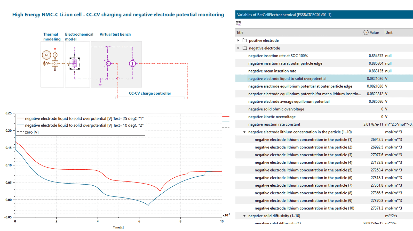
In the image above the “Negative electrode liquid to solid overpotential” detection variable is plotted. For the second simulation case, where the battery temperature was initialized at 10 [°C] instead of 25 [°C], a risk of lithium plating is detected.
Battery Thermal Management System
On a similar topic as to what was just discussed above, a completely new series of battery thermal management demos has been added to the already extensive list of demo models inside Simcenter Amesim. The intention with this set of demo models is to cover many of the topics associated with simulation of battery thermal management in a structured way.
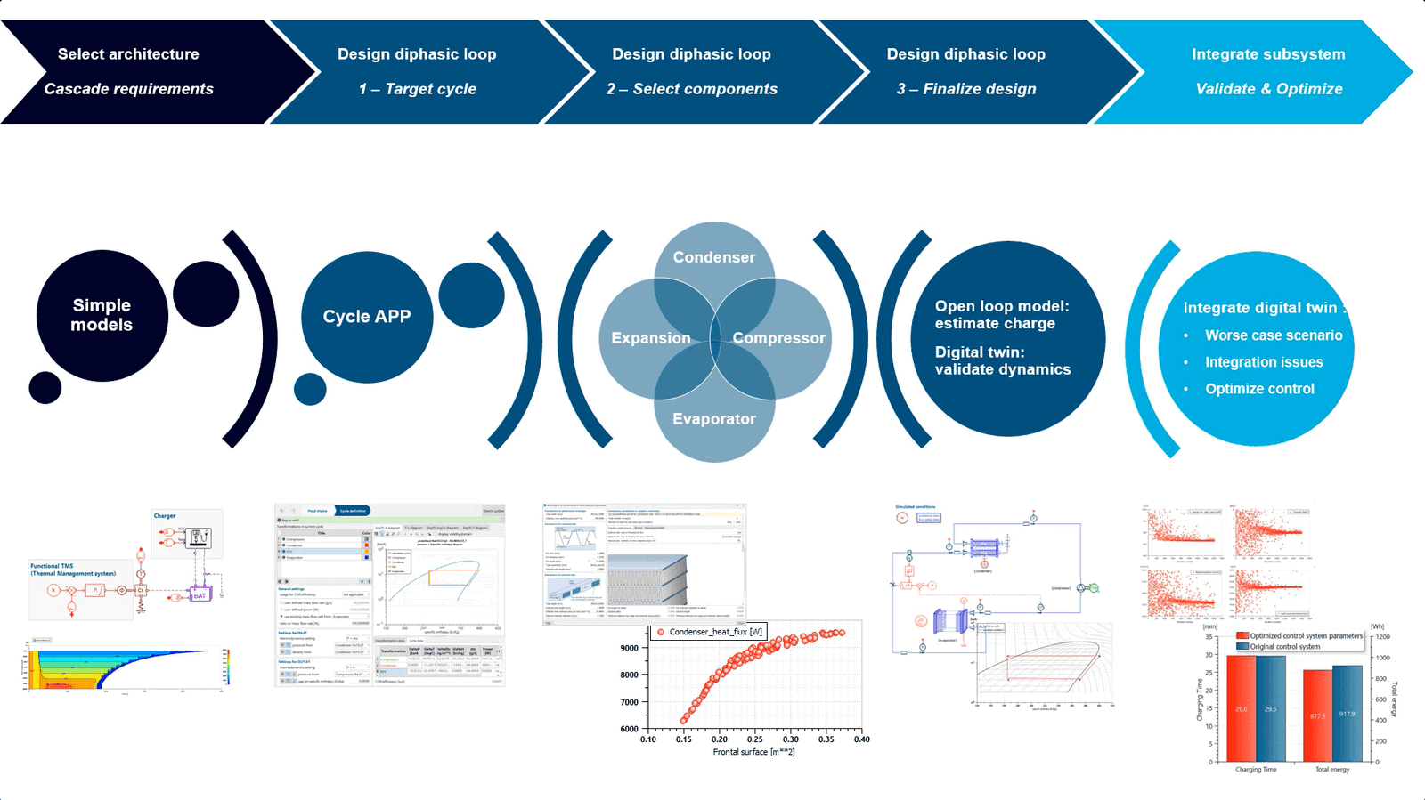
In the initial steps, overall architecture and general requirements, such as charging and cooling, are assessed. Typically, an AC loop is added to modern systems in order to maintain battery temperatures within a reasonable range. This is covered in subsequent steps where a thermodynamic cycle is defined to match the cooling requirements as well as where individual components of the AC circuit are dimensioned accordingly. Following good simulation practices, the final AC circuit is first formed by combining its individual components and then simulated as an open loop system with known boundary conditions. Once satisfactory results are attained, the system is then closed in order to assess the system’s dynamic behavior and to ensure that the system achieves its targets.
In the later part of the demo series more focus is placed on integration and requirements validation. Here, the battery’s electrical model, internal cooling system and the AC circuit are all connected, and control strategies are investigated and optimized. In the system seen below, a fast-running model of the newly created AC circuit is developed to facilitate lightning-fast multi-objective optimization of the control system, showcasing one of many great features inside Simcenter Amesim.

CAD Import
As of version 2310 it is possible to update CAD parts in your simulation model by applying design changes directly to an existing model. This circumvents the need for having to remove the previous geometry, import a new CAD geometry and then having to worry about re-connecting everything in the same order. Once a simulation engineer receives a new design revision the first thing required is to describe the system by associating primitives in the CAD import tool. Then instead of generating the corresponding model to a new sketch, the changes can be applied directly to the preexisting system model allowing you to select what to keep and what to discard.
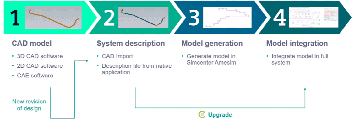
The new feature is available when activating 1D modelling within the CAD import tool and then pressing Model Upgrade. ![]() The intended workflow of the feature is outlined in the image above. The first thing required by Model Upgrade is the model description of the CAD project that will be used to update the model. This can be provided either by using the CAD project currently open in CAD Import, or by supplying a saved description file from an earlier CAD project, typically in the format of .cadmd. In a subsequent step, the new CAD project is then compared to the simulation model currently open in Simcenter Amesim with the purpose of highlighting the differences between the models. This allows users to determine which parts of the simulation model to keep and which parts to discard. The imagery below illustrates an example where new geometry is conveniently added to a system by replacing an earlier CAD revision.
The intended workflow of the feature is outlined in the image above. The first thing required by Model Upgrade is the model description of the CAD project that will be used to update the model. This can be provided either by using the CAD project currently open in CAD Import, or by supplying a saved description file from an earlier CAD project, typically in the format of .cadmd. In a subsequent step, the new CAD project is then compared to the simulation model currently open in Simcenter Amesim with the purpose of highlighting the differences between the models. This allows users to determine which parts of the simulation model to keep and which parts to discard. The imagery below illustrates an example where new geometry is conveniently added to a system by replacing an earlier CAD revision.

We hope you have found this article interesting. If you have any questions or comments, please feel free to reach out to us on support@volupe.com
Author
Fabian Hasselby, M.sc.
