Working with product development usually involves an iterative process analyzing several design proposals. As a CFD engineer, this sometimes means repetitive pre-processing work, as the models need to be prepared for analysis. Using the built-in pre-processor 3D-CAD in Simcenter STAR-CCM+, you can rationalize this process by utilizing the Model Reimport feature. This functionality allows you to replace entire assemblies or parts, while maintaining the 3D-CAD feature tree and re-executing the same operations on the updated design. As such, this tool is ideal for design iteration or even optimization workflows.
Using Model Reimport
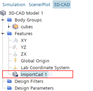
A pre-requisite to use the Model Reimport feature is that you import your original geometry into 3D-CAD. Once you do that, you get an ImportCad feature node in the feature tree.
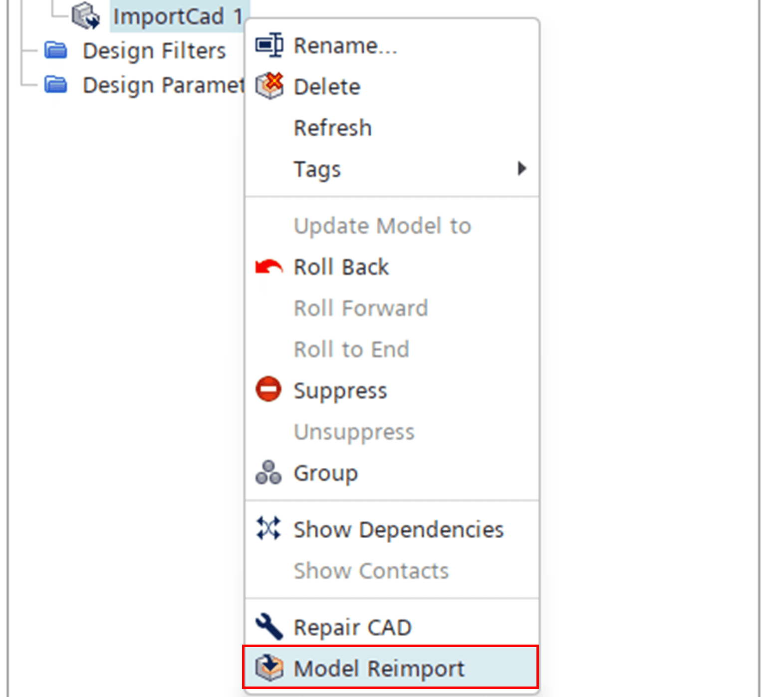
This feature node is where you find the Model Reimport functionality. To replace an imported geometry, you simply right-click the ImportCad feature and select Model Reimport.
In the Open file dialog that pops up, you simply browse to the new geometry file that should replace the existing part. Once you have selected the new geometry file, 3D-CAD interprets the new file and sorts it into four different categories, as depicted below.
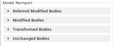
- Referred Modified Bodies contains bodies that were modified, added, or deleted in the new assembly, and for which your input is required to successfully complete the reimport process. This category can list two types of body pairs: Non-matching Bodies or Matching Bodies.
- The Modified Bodies field shows bodies that were successfully matched by 3D-CAD.
- The Transformed Bodies field shows any bodies that may have been transformed in the updated geometry.
- Finally, the Unchanged Bodies shows all bodies that are unchanged in the updated geometry.
The Modified Bodies, Transformed Bodies and Unchanged Bodies are all read-only fields, but you can use them to visualize the different bodies in the 3D-CAD view scene.
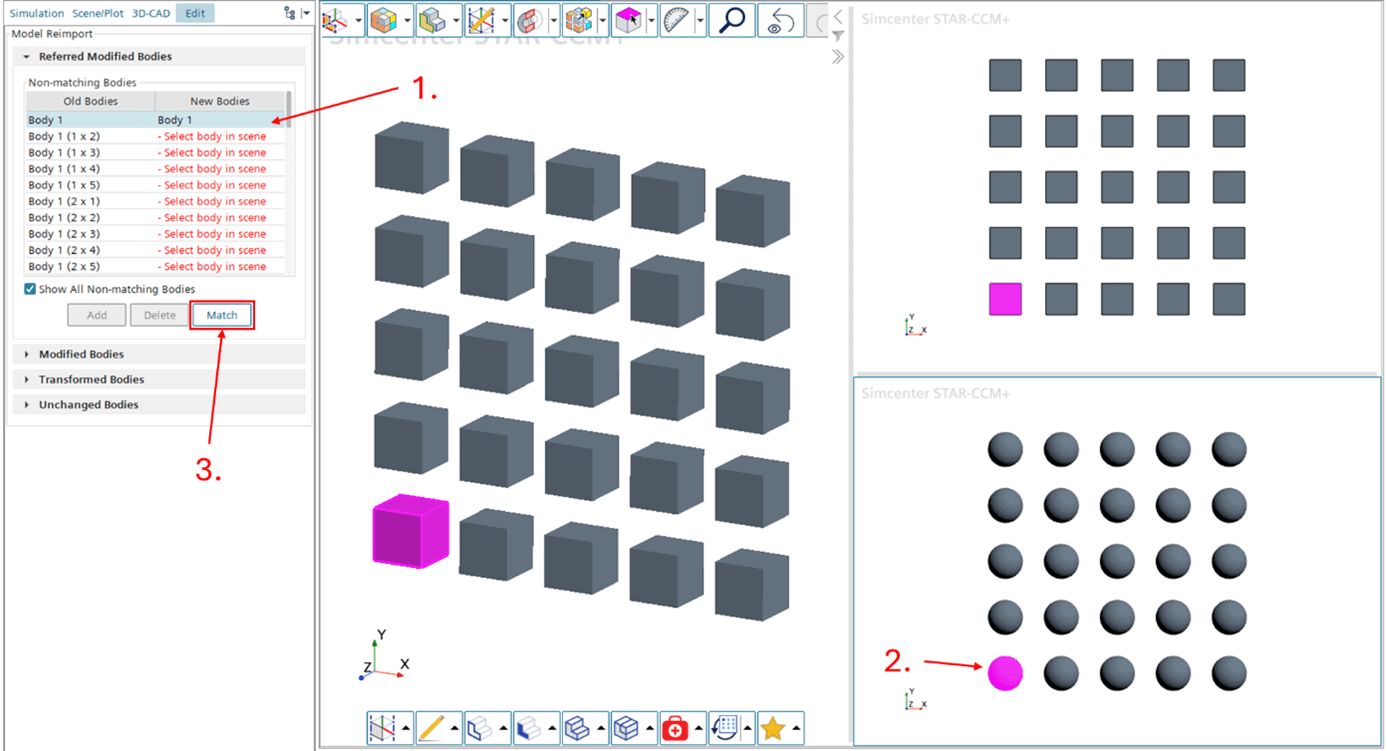
The Non-matching Bodies table (appearing inside the Referred Modified Bodies field) will display a list of bodies that existed in the original CAD but cannot be identified in the new CAD, or bodies that did not exist in the original CAD but are included in the new CAD. To properly replace the parts in the assembly, you need to manually select the relevant parts and match them to each other. In this particular example, we wish to replace a pattern of cubes with a pattern of spheres. The Model Reimport dialog will show a split-scene with the original assembly (in this case the cubes) and the new assembly (the spheres).
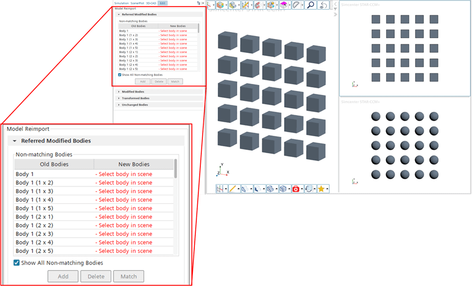
Now you can go through the list of individual bodies in the original geometry and match them with the reciprocal parts of the new geometry.
- Select a row in the table list (the referred original part will be highlighted)
- Select the reciprocal part of the new geometry in the scene
- Click Match
In case there is no relevant corresponding body in the new CAD, and you actually want to retain the original body, you simply select the original body in the table and click Add. In a case where you rather want to remove the original body entirely and not replace it at all, simply select the original body in the table and click Delete.
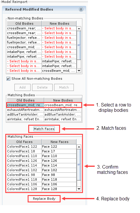
If there is also a Matching Bodies table, this table will contain pairs of bodies that match, but with individual faces that do not match. In this case you would need to manually match the old and new faces, rather than the entire bodies. The picture below shows an example of the workflow for such a scenario.
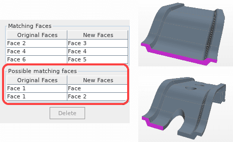
In some cases, the modified geometry may be changed in such a way that there are several faces that are identified as matching with the original one. In such scenarios, there will appear an additional table called Possible Matching Faces (see example below). In this case you resolve the conflict by selecting the faulty face match and click Delete.
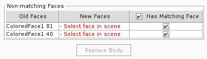
Finally, in some cases 3D-CAD will find a matching body pair, but without finding a match for all the faces. In such a scenario, yet another list will appear: Non-matching Faces. In this case you will need to walk through the list and manually try to find a matching face pair. If you cannot find a matching new face for an original face, then you should untick the checkbox for Has Matching Face for that row. Once you have gone through the list and resolved all the conflicts, click Replace Body.
Note that you need to finalize all the visible steps in the Referred Modified Bodies field in order for the OK button to appear in the bottom of the Model Reimport feature field, but the type of corrections that need to be performed will differ from case to case (depending on the similarity between the files). Once you have finalized all necessary corrections the tables should be empty, and you can click OK to finalize the operation. Once you do so, any downstream manipulation stored in the feature tree will be re-executed on the new design.
I hope you found this description and functionality useful for your simulation work. For more detailed information, the usage of Model Reimport is also well-documented in the Simcenter STAR-CCM+ User Guide (https://docs.sw.siemens.com/documentation/external/PL20240730373082998/en-US/userManual/starccmp_userguide_html/STARCCMP/GUID-700AA8D1-7FC0-430B-B8BB-673EB0E91286.html?hl=model%2Creimport). It may also be relevant to investigate the “Replace Part” operation, which has been described in an earlier blog post (https://volupe.com/simcenter-star-ccm/replace-part-with-simcenter-star-ccm/). As always, if you have any questions, please contact us at support@volupe.com.
Author

Johan Bernander, M.Sc.