We are back with badminton shuttle simulations at the Volupe blog. This time we will look at how the shuttle is turning just after the hit with the racquet, which requires the moment of inertia (MOI) and center of mass (CM) to be accurate. Chalmers University of Technology is investigating these properties in a bachelor thesis project, so we will get correct values to use soon. Preliminary numbers from Chalmers and previously measured values from other institutions are used so far. In addition, we will look into the workflow of deformable flexible bodies in free motion within Simcenter STAR-CCM+.
Turning of shuttle
In the previous blog post about badminton shuttle simulations [https://volupe.com/simcenter-star-ccm/badminton-simulations-in-simcenter-star-ccm/] we were looking at a serve trajectory. The shuttle properties of mass center and moment of inertia was important already then, but now when the shuttle will be turning, it will be even more important and to capture the physical behavior of the shuttle fluctuating into its path with overshooting and undershooting the feather position compared to the position of the cork (like an underdamped door in oscillation). See slow motion video below and note when the shuttle is rotating into position with the cork in front and the fluctuations afterwards.
Thanks to my friends Hjalmar (hitting the shuttle) and Fredrik (serving, not in picture) for managing to repeat a strike of shuttle pointing downwards 10 degrees and hitting the shuttle horizontally. To be able to compare the video with my simulations. Just to mention it, the video is mirrored, to be in the same direction as the simulations, making the shuttle look like it is rotating in the opposite direction.
Simulating the event of a shuttle turning using the two different moments of inertia is visualized below. The first video below is using Lin values.
And the second video is instead using Chalmers (previous) values.
Comparing the two videos of simulation results, they are very similar. The fluctuations/oscillations might be captured a bit better when using Chalmers MOI and Lin might capture the direction of the cork not pointing in the flow path direction in all instances. To determine which MOI is most correct more experiments and simulations will be needed. Data from simulations need to be extracted to be able to quantify the turning behavior.
Tumbling of a shuttle
Further investigation is needed, and by looking at a strike where more rotation in all directions is generated the correct MOI will hopefully prove much better results than when using an incorrect MOI. The phenomenon that meets this criterion is when the shuttle is tumbling.
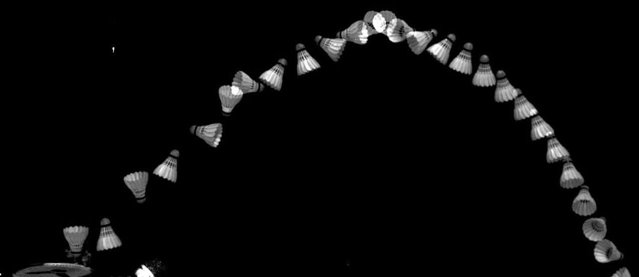
A tumbling short net shot in badminton is when the shuttle is falling downwards, and the racquet hits the shuttle from below and gives it a spin in a direction that makes it rotate in a chaotic way, not only in the direction of the rotational symmetry axis. When the center of pressure (CP) is not aligned with the center of mass and the rotational symmetry axis as in this (and the turning) case, the shuttle will need time to oscillate into a stable flow path. In the picture below you see that the orientation of the shuttle changes a lot for this type of strike, which will hopefully be the perfect case for analyzing the MOI impact on the shuttle trajectory.
As a further study of MOI a video of a tumbling short net shot will be recorded and then simulations will be carried out to match the experiment. Which initial conditions to use are always difficult when you cannot measure the force applied, but hopefully results will show enough characteristic behavior. Also, Chalmers’ new results for MOI determined in the bachelor thesis need to be considered as a potential third simulation to compare with. Data from all simulations will be extracted and analyzed, since videos alone give too subjective conclusions.
FSI workflow using deformable DFBI bodies in free motion
Previously the setup covered DFBI bodies and overset mesh, and when adding a solid region with Fluid solid interaction (FSI) there are both new properties to set and new connections between regions. This will allow the shuttle to be flexible, according to the material properties, and the fluid region to morph around the solid region in all time steps. Solid stresses and displacements of the solid body are calculated based on how the fluid flow around the shuttle is calculated from Navier-Stokes equations.
Steps to implement the free deformable DFBI workflow in your simulations, from when assigning your parts to regions:
- Creating regions:
- When creating the regions, no interfaces should be created automatically.
- One region for your solid body, one for the overset mesh and one for the background mesh.
- Outer boundaries of the overset mesh should be set to overset mesh boundaries.
- Select the overset region and background region, right-click and create new overset mesh interface (Alternate hole cutting and Close proximity is often best to activate).
- Creating continua:
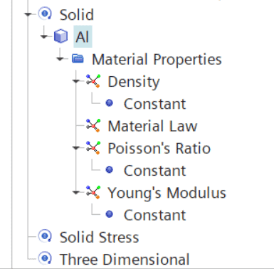
- Create the fluid and the solid continua and assign it to the corresponding region.
- Set up the correct material properties for the solid region (density and Young’s modulus etc).
- FSI set up:
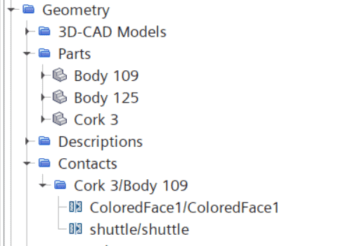
- Use contacts in Geometry -> Contacts, right-click Set interface -> New. Make sure that the contact icon changes and adds a small arrow indicating that it is an In-place contact between two part surfaces with Mapped contact interface. Double check that contact is of type conformal, and the interface is of type Mapped contact interface.
- DFBI set up:
- Follow the setup as described in the previous blog post, with adding a DFBI rotation and translation in Tools -> Motions, setting your DFBI properties (CM and MOI etc). All degrees of freedom should be active, so the shuttle can move freely.
- Use initial condition of velocity instead of applying a force, since we will simulate a free deformable DFBI body.
- Deformable DFBI set up:
- In the continua for the solid, select the Flexible DFBI motion model.
- For the solid region, in Physics conditions -> flexible DFBI motion option, set “DFBI – deformable body“.
- Right-click on the DFBI body and Create body motion. A new motion is added in Tools -> Motions.
- Right-click on the subfolder for the motion named Superposing motion and add New -> Solid displacement.
- In your solid region -> Physics values -> Motion specification, select this superposing solid displacement motion.
- In Tools -> Motions, create a new DFBI morphing motion.
- This morphing motion should be selected in your overset region at Physics values -> Motion specification.
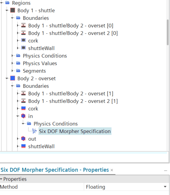
- For the mapped contact boundaries in the overset region towards the solid, select the Six DOF morpher specification to be “Six DOF body”. So these boundaries are displaced both according to the solid displacement and the DFBI body motion.
- For the overset mesh boundaries, towards the background region, select the Six DOF morpher specification to be “Floating”. So these boundaries follow the DFBI body.
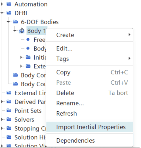
- Import initial properties for your DFBI body (right-click on your DFBI body and select Import initial properties). Calculated values from CM and MOI are used since the DFBI body needs to be connected to your solid body properties.
Pictures below are provided as a complement to the bullet point list above, to make it easier to follow the steps in the bullet point list:
Icon for In-place contact between two part surfaces with Mapped contact interface.
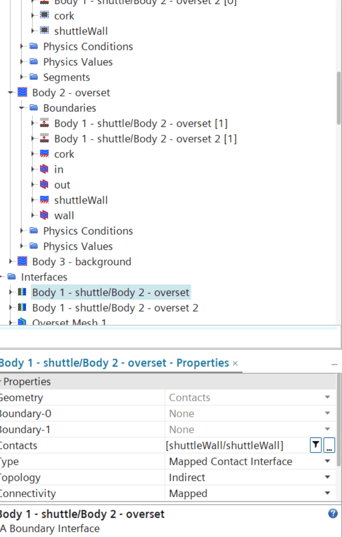
Mapped contact interfaces visualized in Interfaces, and in the Regions you see the icon for mapped contact boundaries.
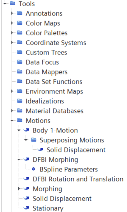
Motions for this set up of DFBI body motion, where superposed motions are needed for the deformable body having both a motion and a solid displacement.
Six DOF morpher specification set to Floating for the overset mesh boundaries.
When using a flexible deformable DFBI body, you must use the calculated initial values for the body based on material properties (specified in the continua for the specific region that belongs to the solid bodies).
Note: since I don’t have the material parameters for cork and feathers to use at the moment, I have used the default material Aluminum as base for the material properties and modified the density to 1/10 of the default value (this is now for the whole body, in a later stage the cork and feathers will be split into two regions with different material properties), as temporary user input. Which gives a density of 270.2kg/m^3 and Young’s modulus still at 6.8E10Pa. Lowering the value for Young’s modulus would provide a more flexible shuttle, and more accurate results, which will be investigated in the coming simulations. Getting these types of data from experiments would provide good conditions for simulating the shuttle accurately. This value for density results in quite similar CM and MOI as have been used before, therefore this value of density was used. CM is a bit further back towards the feather tips, since in reality the feathers are very light, making the CM being closer to the cork. MOI is instead [2.3451346063370464E-6, 5.457929471390371E-6, 5.45792432213239E-6] kg-m^2, which is a bit higher than the previous values, making the shuttle a bit more difficult to rotate. The mass is also calculated, in this case to 6.6g instead of 5.2g.
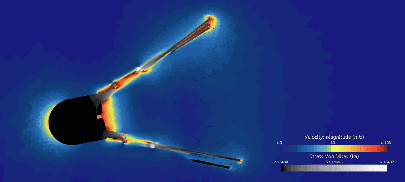
In the picture (a snapshot in time) below you see the first results from the DFBI+FSI workflow. This is very early in the movement where high stresses and velocities occur. Note the high stresses in the rings holding the feathers in place, and the high velocities between the feathers where the gap is small.
Notes about mesh resolution
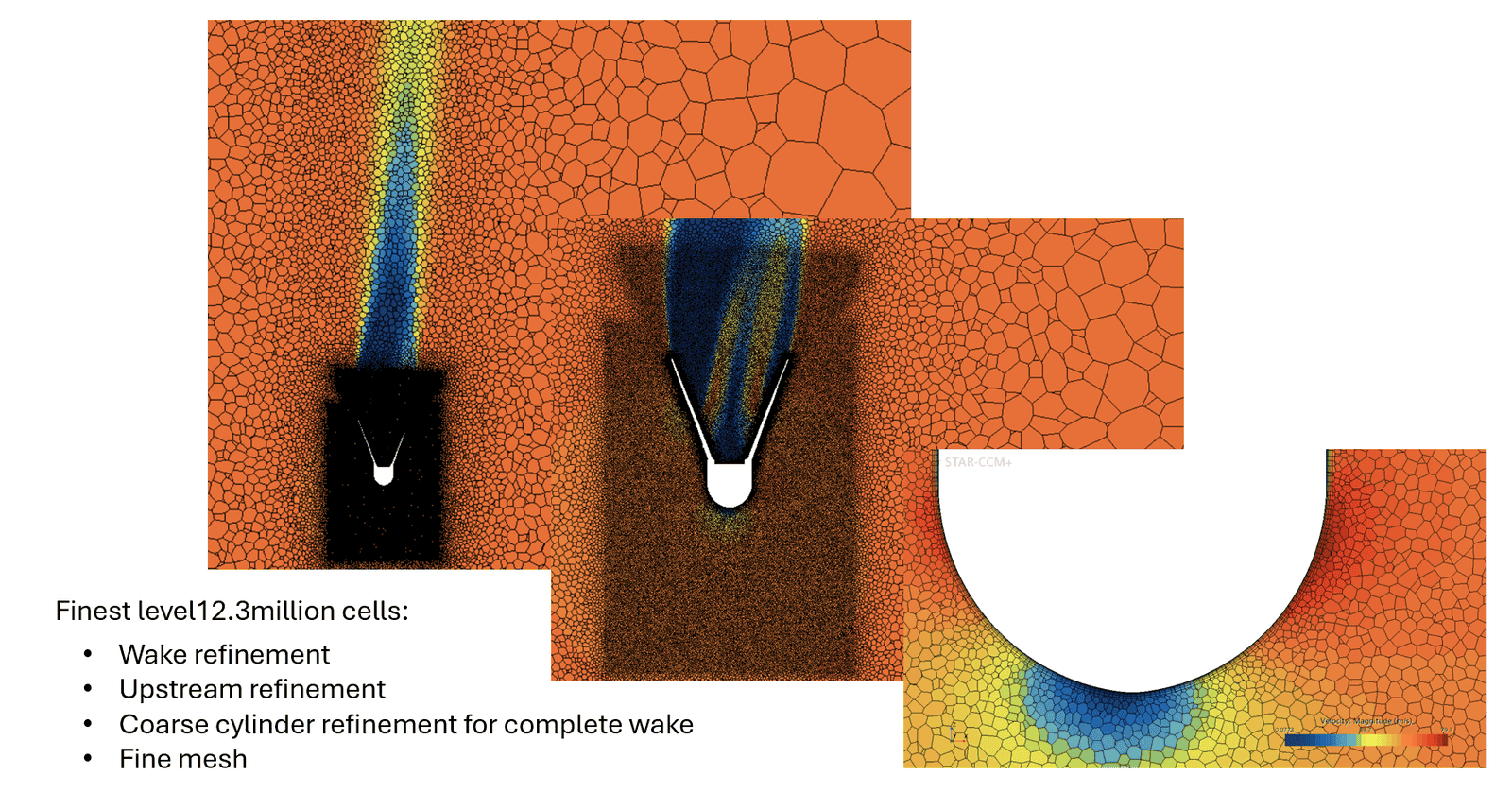
Mesh resolution is always important to ensure that the simulation results are mesh independent. In the previous blog post this was discussed in quite deep detail. Additional mesh studies have been carried out to investigate if the results are accurate enough. The conclusions are that to get completely mesh independent results an upstream refinement together with a (quite coarse) cylinder refinement for the complete wake flow is required. See picture below from the test case where force was measured on the shuttle in steady state (with three different zoom perspectives, trying to show the resolutions in all areas). Previously the wake refinement together with fine mesh settings have been used, which provides good results as well but a small increase in accuracy will be obtained if the new refinements are introduced.
 To double check that the previous trajectory results are accurate a simulation with finer mesh has been started, but results have not been obtained yet. The results from turning and tumbling of shuttles will be run with finer mesh than presented in this article to ensure more accurate results and that all differences in properties will show.
When it comes to FSI simulations both time step and mesh resolution are needed to be of finest resolution, therefore this simulation will need much computational power. It will be very interesting to compare trajectories with rigid boundaries to FSI results with deformable bodies and see how much the flexibility of the shuttle increases the distance travelled – this is one of the upcoming simulations that we hope to present within not too far future.
Thank you for reading this blog post about badminton shuttles, we hope that it was interesting and that you are able to use the set up for your deformable DFBI bodies in free motion in your simulations. If you have any questions about your simulations, feel free to reach out at support@volupe.com.
Author
Christoffer Johansson, M.Sc.
support@volupe.com
+46764479945