Simcenter Simsolid with Multi-loadcases
How to utilise the Multi-loads set-up in Simcenter Simsolid.

Johan DahlbergApplication Support Specialist
In short
In this blog we look into the Multi-loadcase feature and some of the post processing features connected to multi-loads
This blog explores SimSolid’s Multi-loadcase feature, one of its analysis options for structural simulation. We focus on generating load cases or subcases using loads imported from a CSV file.
Importing loads lets you quickly set up standardised analyses and run them all at once. Once the results are available, you can create an envelope across all load cases to identify the most severe loading scenario. For this example, we use what appears to be a quadcopter drone frame from the standard tutorial package, SS-T: 3015 Imported Remote Loads on Specific Faces. You can access the model from Simcenter Support, attached link here:
support.sw.siemens.com/en-US/product/283778410/download/PL20260205322695233
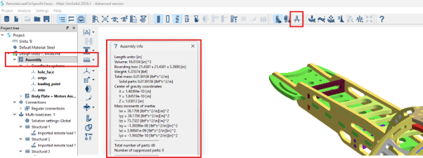
It measures 21.5 inches in width (wingspan) and roughly 4inches in height. To get detailed model information one can right-click on Assembly and select info, or one can manually use the measuring tool to measure various model distances.
Zooming out a bit, the entire model look like this, the origo is at the bottom center. The different loading points are denotedPoint1-4
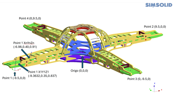
The provided loading table is current defined as two loadcases, with loads in each motor positions, denoted Structural 1 and 2. The first XYZ are the load position, F/M and are the applied loads, here only Fz is used. The additional X1Y1Z1 and T1 to XnYnZN and Tn are options for adding additional tangential surfaces to the load selection. If only the first XYZ are specified, the remote load will be applied at the area center of the nearest surface. So, in this case we have loading in four different locations which are applied simultaneously in Structural 1 and 2.

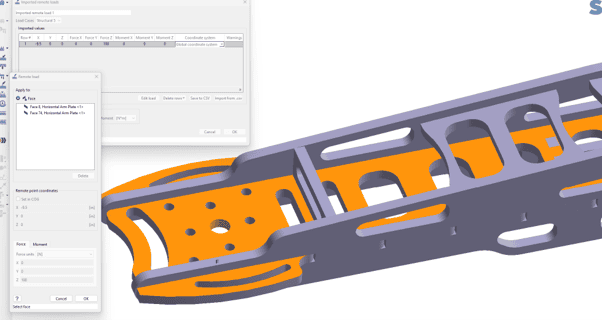
To sort out the different options for specifying the remote loads, we initially will study point 1 with some different loading configurations. So, we will use the Point 1 + the additional Point 1 X1Y1Z1 and XnYnZn in figure above.
Load 1 – only XYZ defined: Double click on the row in order to highlight the remote load and where it is attached. In this case the defined remote load point was closest to the arm bottom side and therefore highlighted
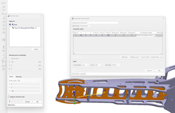
Load 2 – XYZ + X2Y2Z3 defined, since we have added the surface of the hole, It attached the remote load to this surface.
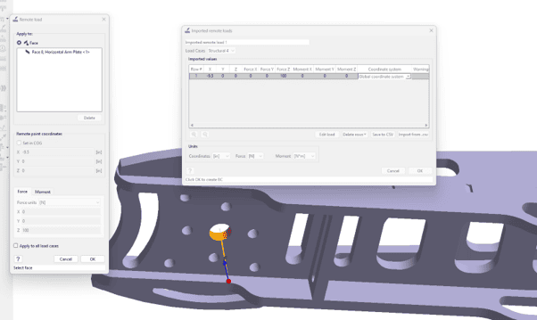
Load 3 – XYZ + X2Y2Z3 + T options. We now also add a 3thrd point on the arms upper face. Since that face is tangential to the hole surface it will be added to the selection of load application surfaces
The three above options look like this in csv input, here added to the original loading list as structural 3, 4 and 5

Going back to the given original .csv file with two structural loadcases, since the face of the holes are specified for structural 1 the remote load will be applied to surface center / hole center
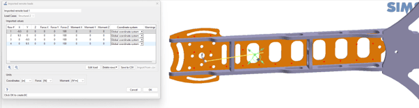
Structural 2 has no extra information, so the load will be applied to nearest surface
Structural 1
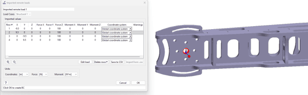
Structural 2
Solving the problem with solution setting set to Global+local. All parts have the default steel applied as material and the 2 top circular face are set to be immovable support, see yellow markers in figure
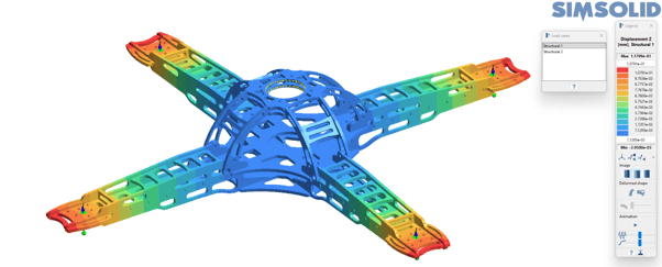
In this example, the Z-direction displacement is similar for both load cases: 0.118 mm for Structural 1 and 0.116 mm for Structural 2.
To explore a wider range of loading conditions, we have kept the load application points unchanged while varying the load magnitudes and including Fy, Fz, Mx, My, and Mz components across 11 load cases.
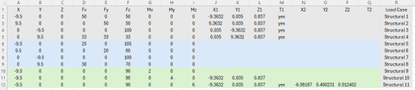
Note how the loadcase list is populated once you hit accept on the import of remote load button
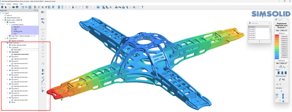
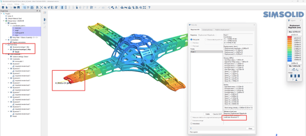
Now the displacement variation is much larger, and spans between 0.119 mm to 0.338 mm for the last, maximum occurred for loadcase 10
For this set of result, we can now utilise the post processing tool, Envelope
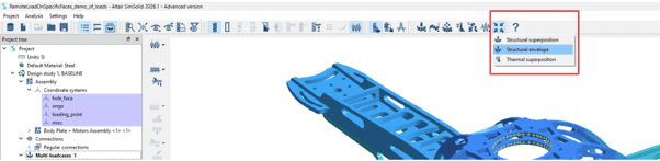
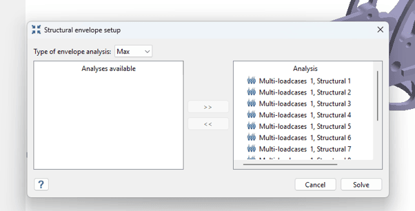
Solving for all cases and then postprocess, here the pick info on point have been utilized to get information about which load case has resulted in largest displacement.
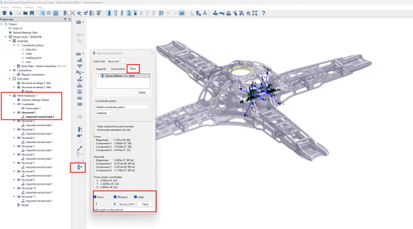
Going back to the individual multi loadcases one can for each and single case investigate reaction and contact forces at part level, toggle to part option and select one or several parts to investigate.
I hope this blog have giving you some insight how to get as much as possible out of linear multi-loadcases performed in Simcenter Simsolid, the simulations are carried out in Simcenter SimSolid 2026.1
As always, if you have questions about any other product in the Simcenter simulation portfolio, you can send us questions at support@volupe.com