Beam, shell or solid elements in Simcenter Femap
When to use beam, shell or solid elements in Simcenter Femap, and how to set up beams, plates for thin walls and tet or hex solids.
In short
Use beam elements in Femap for long, slender members, shells for thin walls and solids for thick parts and local details. When in doubt, decide by the result you need: stiffness and load paths from beams and shells, the stress in a fillet radius from solids. For stress results in solids, use parabolic tetrahedra.
With an automatic tetrahedral mesher you can quickly fill almost any CAD model with solid elements. That does not make solids the right choice every time. The element family decides the size of the model and the solve time, but more importantly it decides which results you can trust. In this week’s blog post we go through the three families in Simcenter Femap (beams, shells and solids): when each one fits and how to set it up for Simcenter Nastran (formerly NX Nastran).
Beam, shell or solid? Start with the load path
The modelling guidelines in the Simcenter Nastran documentation warn about a common mistake: modelling only the geometry of a part instead of both its geometry and how it physically behaves. So before you pick an element, ask what the structure does: does it carry load along a slender member, bend as a thin wall, or have stresses that change in all three directions, as in a thick casting? A hand calculation of the main load path usually tells you, and for a single member our beam calculator gives the reactions, bending moment and deflection.
When the answer is not obvious, decide by the result you need. Stiffness, load paths and natural frequencies of the whole structure come out well from beams and shells, and the model stays small enough to run many load cases. For the peak stress in a fillet radius, or wherever the stress changes through the thickness (at a 3D joint, for example), you need solids, at least locally. You can also have both: shells and beams for the structure and a solid region for the critical detail.
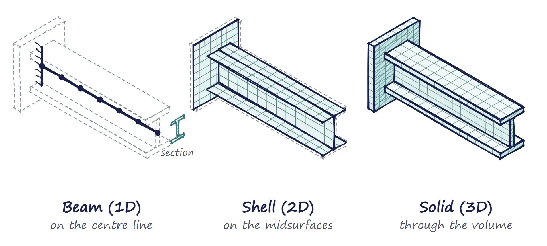
Figure 1: The same welded I-beam bracket modelled with beam elements on its centre line (the end plate becomes a fixed support), shell elements on its midsurfaces and solid elements through the volume.
Our finite element analysis guide covers the element types in general; here we stay with Femap.
| Family | Use it for | What you give up | Femap elements | Nastran entries |
|---|---|---|---|---|
| Beam (1D) | Frames, trusses, stiffeners | Local stresses at joints and holes | Rod, Bar, Beam | CROD, CBAR, CBEAM |
| Shell (2D) | Thin walls: sheet metal, plates, mouldings | Through-thickness stress; 3D stress at fillets and joints | Plate (and Laminate) | CQUAD4 and CTRIA3; CQUAD8 and CTRIA6 with midside nodes |
| Solid (3D) | Thick parts, fillets, local details | Small, fast models; thin walls usually need several elements through the thickness | Solid | CTETRA, CHEXA, CPENTA, CPYRAM |
Beam elements: rod, bar or beam
Femap has several line elements, tubes and curved beams among them. The three general ones are the rod, the bar and the beam. A rod carries tension, compression and torsion but no bending or shear, which makes it the element for trusses and pin-ended members. A bar adds bending and is the general element for frames. A beam does the same as a bar, but it can be tapered, with different properties at each end, and its property also takes a warping constant and neutral axis offsets.
CBAR or CBEAM?
Our rule of thumb for Simcenter Nastran: CROD when a member only carries axial load or torsion, and CBAR as the default for bending, since it is easier to set up. Switch to CBEAM when the section is tapered, when the neutral axis and the shear centre do not coincide (open sections such as channels), when warping affects the torsional stiffness, or when the centre of mass is far from the shear centre. CBEAM needs non-zero values for both I1 and I2. If you come from another program, check the convention: in Femap, I1 is about the element Z axis and I2 about the Y axis.
Cross sections and orientation
The Shape button in the bar or beam property (Model → Property) opens the cross-section generator, which calculates the area, the moments of inertia, the torsional constant, the shear areas and the stress recovery locations. If you type the values in yourself, enter the effective shear area rather than a shear factor, and fill in the stress recovery locations too: they are the points where Simcenter Nastran reports the beam stresses.
Orientation is easy to get wrong. The element X axis runs from the first node to the second, and an orientation vector (or a third node) sets which way the element Y axis points, and with it how the section is turned.
Mesh → Geometry → Curve uses one orientation vector for every element it creates, unless the curves carry mesh attributes. With Mesh → Mesh Control → Attributes Along Curve each curve gets its own property, orientation and offsets. To correct elements afterwards, use Modify → Update Elements → Line Element Orientation; its Radial option is for sections that must turn with a curve, such as a ring stiffener on a cylinder.
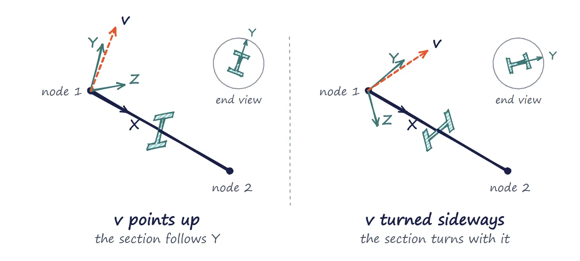
Figure 2: The orientation vector v sets the element Y axis. The section lies in the element Y–Z plane, so turning v turns the section with it.
The easiest check is visual: in View → Options, under Labels, Entities and Color, choose Element – Orientation/Shape and set Element Shape to Show Cross Section. Femap then draws the real section on every bar and beam whose section was made with the Shape button, and an I-beam lying on its side is obvious at a glance. It takes a few seconds, so we simply do it every time. A bonus tip: the Element – Beam Y-Axis option in the same list draws the true element Y axis, which helps with round bars and tubes, where the drawn section looks the same whichever way it is turned.
For a stiffener on a plate, give the section a reference point and mesh the curve with Offset to Reference Point. The plate nodes sit on the plate’s midsurface, so add half the plate thickness to the offset.
Shell elements: plates for thin walls
For thin-walled parts we normally start with plate elements, which is what Femap calls its shell elements. A plate carries membrane, shear and bending loads, as a 3- or 4-node element or as a 6- or 8-node element with midside nodes. The thickness is set in the plate property, as one value or one value per corner, and the element can be offset from its nodes along its normal.
Most CAD models arrive as solids, so the shell model starts with a midsurface. It is worth the work: according to the Femap documentation, a midsurface model of a thin-walled part can be an order of magnitude smaller than a solid mesh of the same wall, and in most cases more accurate. Geometry → Midsurface → Automatic builds the midsurfaces, and Geometry → Midsurface → Assign Mesh Attributes gives each wall of constant thickness a property with the right thickness. Where the thickness varies, mesh first and then use Modify → Update Elements → Midsurface Thickness and Offset.
Expect some manual clean-up on real castings and mouldings, and check the result in the Free Edge style of View → Select: away from the outer boundary, a free edge usually means a gap between plates. Our post on midsurfaces in Femap and Simcenter 3D shows these commands with videos.
For a part with one constant thickness there are two shortcuts. Mesh the inner or outer face and move the elements to the midsurface with Modify → Move By → Offset Element (Normals with Thickness Correction). Or keep the nodes on the outer face, for example to share them with a mating part, and give the plates an offset of half the thickness with Modify → Update Elements → Adjust Plate Thickness/Offset.
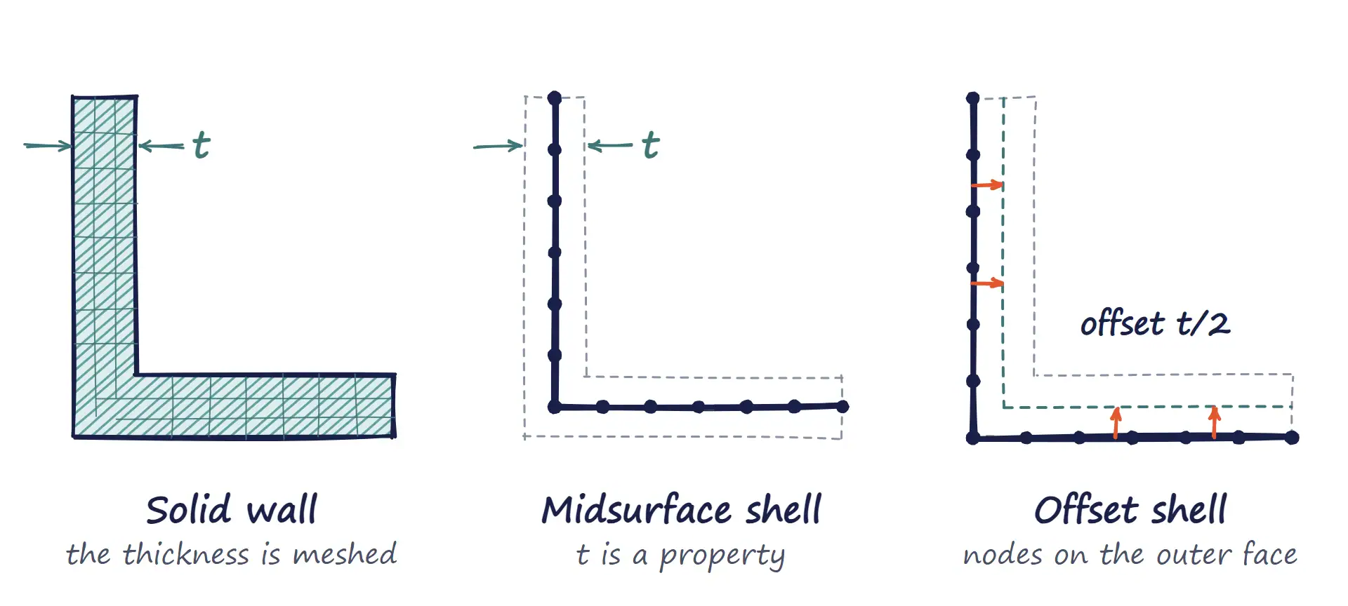
Figure 3: A thin wall meshed with solids (left), with plates on the midsurface and the thickness t as a property (middle), and with plates whose nodes sit on the outer face, offset by t/2 (right).
Prefer quadrilaterals for the plates. CTRIA3 is a constant-strain element, stiffer than CQUAD4 and less accurate, particularly for membrane strain, so keep triangles to the places where the geometry needs them. Avoid highly skewed, elongated and warped elements, and do not connect parabolic plates to linear ones. Split critical areas into four-sided surfaces where you can, since Femap gives them an all-quad mapped mesh. Tools → Check → Element Quality lists the distorted ones, and its Simcenter Nastran tab uses the solver’s own checks.
Finally, check the normals. Pressure, plate offsets and the top and bottom stresses all refer to the element normal. On a folded part, Modify → Update Elements → Orient Normal/Orient First Edge aligns all the normals in one go, and the Element – Direction view option shows the result.
Solid elements: tetrahedra and hexahedra
Femap’s solid element covers the 4-node tetrahedron, 5-node pyramid, 6-node wedge and 8-node hexahedron, and the parabolic versions with 10, 13, 15 and 20 nodes. The Parabolic Elements option on the element type adds the midside nodes.
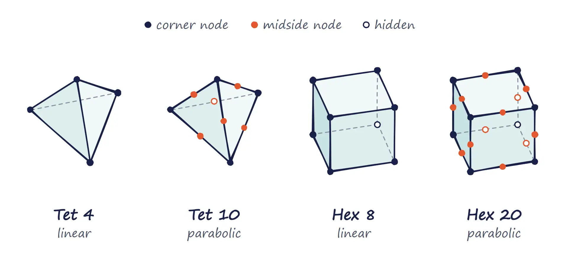
Figure 4: Linear and parabolic tetrahedra and hexahedra. The parabolic versions add a node in the middle of every edge.
Tetrahedra for complex parts
For complex parts with holes and many features, the automatic tetrahedral mesher is the practical route, and running Mesh → Geometry Preparation first gives better tetrahedra. For stress results we use parabolic (10-node) tetrahedra. The Siemens Knowledge Base notes that the 4-node tetrahedron is too stiff, especially in bending, and recommends the parabolic (second-order) version as the default. The Midside Nodes on Surface option in Mesh → Geometry → Solids moves the midside nodes onto curved geometry.
Hexahedra: hex-dominant or all-hex
The quick route is Mesh → HexMesh Bodies, the hex-dominant mesher. It fills the solid with as many hexahedra as it can and the rest with wedges, pyramids and tetrahedra, without splitting the geometry first, and it reports how much of the volume became hexahedra. Check that the tetrahedra and pyramids did not end up where you read the stresses.
For an all-hex mesh the work is in the preparation:
- Slice the part into hex-meshable pieces (six-sided blocks, extruded and revolved shapes) with Geometry → Solid → Slice.
- Size all of them in one operation with Mesh → Mesh Control → Size on Solid and the Hex Meshing option. Sized separately, the pieces will not match.
- Mesh with Mesh → Geometry → HexMesh Solids.
Where only part of a model can be hex meshed, use the Tet/Pyramid Mesh approach for the rest; Femap puts pyramids at the transition. If the tetrahedra are parabolic, make the hexahedra and pyramids parabolic too, so the midside nodes connect.
Shell or solid for a thin wall?
Use shells, and add a local solid region only where you need the stress in a fillet radius or through the thickness. To capture bending in a thin wall with solids you usually need several elements across the wall, and very thin hexahedra or wedges, used in place of shells, are prone to round-off errors.
When you mix the families
Mixing is common, and that is where the next trap is. Solid elements only have stiffness in the three translations at their nodes, so a plate that only shares nodes with a solid behaves like a hinge, and a beam like a pin. In a follow-up post we show how to tie the families together in Femap with RBE3 elements or edge-to-surface glue, and which checks we run before and after the first solve.
We hope this post makes the first modelling decision a little easier the next time a new CAD model lands on your desk.
Sources: Simcenter Femap 2606 documentation (User Guide, Commands Guide), the Simcenter Nastran User’s Guide and the Siemens Knowledge Base.