Connecting shells and beams to solids in Simcenter Femap
Why a shell or beam on a solid acts as a hinge, how to tie it in with RBE3 or edge-to-surface glue in Simcenter Femap, and which checks to run.
In short
Solid elements have no rotational stiffness, so a plate or beam that only shares nodes with a solid acts as a hinge or a pin. In Femap, tie it in with an RBE3 element or glue the shell edges to the solid faces. A free-free modal run can show a missed hinge as a seventh mode near 0 Hz.
Real models are rarely made of one element family. A solid casting carries welded plates, or a shell model gets a solid region where the stress in a fillet matters. In our post on beam, shell or solid elements in Simcenter Femap we went through when to use each family. In this week’s post we look at how to connect shells and beams to solids in Simcenter Femap for Simcenter Nastran, and at the checks we run before and after the first solve to make sure the joints work.
Why a shell or beam on a solid becomes a hinge
The catch is in the degrees of freedom. Solid elements only have stiffness in the three translations at their nodes, not in rotations. Beams and plates (Femap’s shell elements) do. So if a plate only shares nodes with a solid, nothing stops the plate from rotating about that line of nodes: the joint behaves like a hinge. A beam end on a single solid node behaves like a pin. The Simcenter Nastran documentation lists such joints among the typical causes of mechanisms and singularities.
What happens next depends on the rest of the model. If the plate is also held somewhere else, the model still runs and the hinge is easy to miss: it is the kind of error that does not shout. If the joint is its only support, as in Figure 1, the static solve stops with fatal message 9050 about excessive pivot ratios.
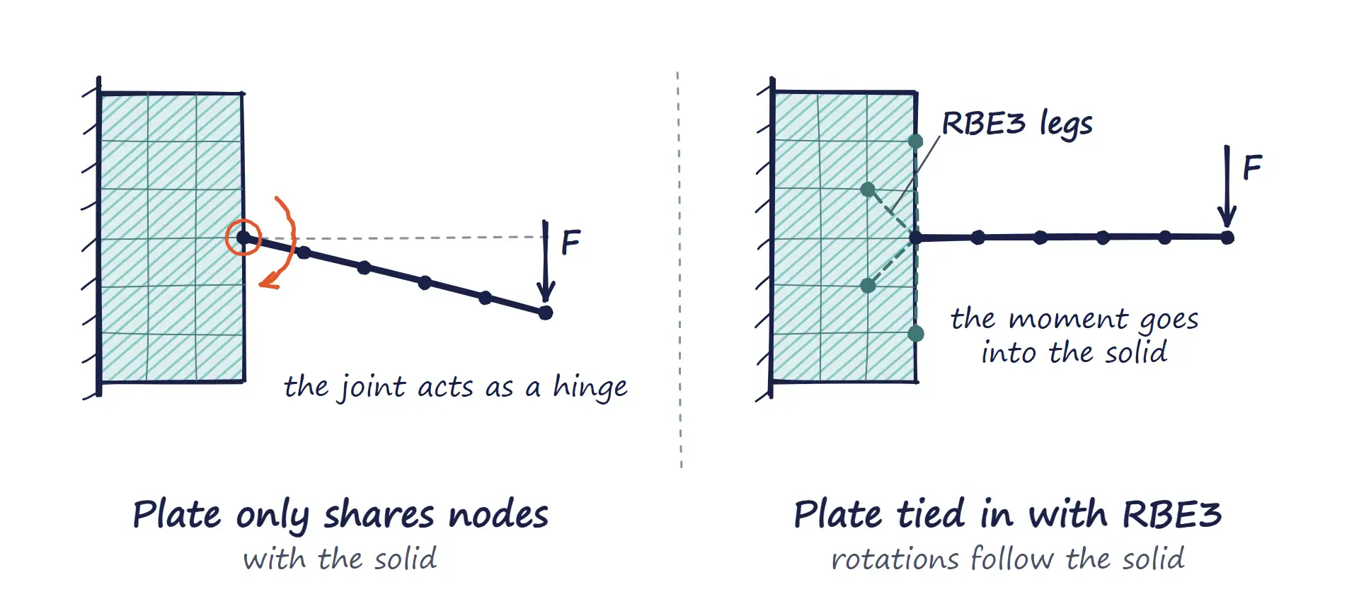
Figure 1: A plate that only shares nodes with a solid acts as a hinge. RBE3 elements tie the plate’s rotations to the solid’s translations, so the moment goes into the solid.
RBE2 or RBE3: tying shells and beams to solids
Femap creates RBE2 and RBE3 elements with the Rigid element type, whose dialog has one tab per Simcenter Nastran entry, but they work very differently: an RBE3 spreads a load without adding stiffness, while an RBE2 makes the tied region rigid.
RBE3 elements
The usual fix is an RBE3 element, made on the RBE3 (Interpolation) tab. It ties the rotations of the plate or beam node to the translations of the solid nodes around it.
Pick TX, TY and TZ of the surrounding solid nodes as independent. If the plate or beam node is shared with the solid, make only its RX, RY and RZ dependent. If it is a separate node, make all six of its degrees of freedom dependent. The independent nodes must be able to stop any rigid-body motion on their own; for a beam end that means at least three nodes that are not on one line.
Because the dependent node moves as a weighted average of the independent nodes, the RBE3 is a good default for bringing a beam or plate load into a solid.
RBE2 elements
An RBE2 ties the dependent nodes rigidly to one independent node. Use it only when the joint is rigid: it also makes that part of the solid rigid. On the RBE2 tab, New Node At Center creates the independent node in the middle of the selected nodes, which is how we build a spider in a bolt hole. With temperature loads, give the rigid element a coefficient of thermal expansion as well (the Rigid dialog has a field for it, or use Modify → Update Elements → Rigid Thermal Expansion); without one it holds the tied region at its original size.
The Simcenter Nastran guide also mentions a third way, without rigid elements: let the plate or bar continue into the solid, so that the extra elements carry the moment. It needs matching nodes, so it suits a mapped or hex mesh best.
Edge-to-surface glue when the meshes do not match
When the plate mesh and the solid mesh do not line up, which is the normal case with an automatic tetrahedral mesh, glue is the easier route. Simcenter Nastran’s edge-to-surface glue connects the edges of shell elements to the faces of shell or solid elements and carries both forces and moments. It projects the shell edge onto the target faces and connects the points that lie within a search distance you set, so the meshes do not have to match. It works on shell edges only; for a beam end, use an RBE3 or RBE2.
In Femap it is set up on the Connect menu:
- Connect → Connection Property, with the Type set to Glued.
- Connect → Connection Region on the shell edges, with Output set to Nodes, and a second region on the solid faces.
- Connect → Connector between them, with the edge region as the source.
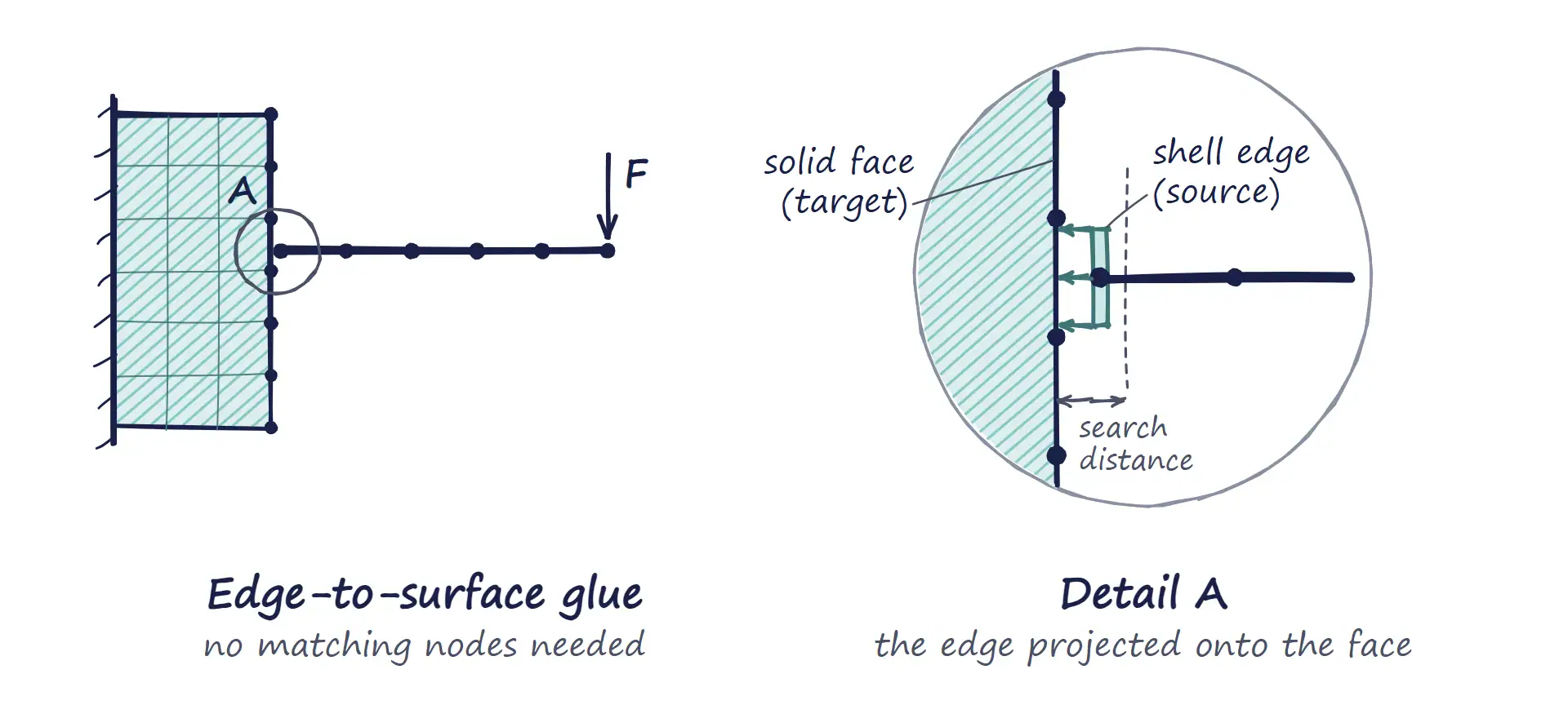
Figure 2: Edge-to-surface glue. Points on the shell edge (source) are projected onto the solid face (target) and glued where they fall within the search distance.
Choosing the connection
To sum up, this is how the four options compare:
| Connection | Use it for | Matching mesh? | What to watch |
|---|---|---|---|
| RBE3 | The default for bringing a beam or plate load into a solid | No; the plate or beam node can be shared or separate | The independent nodes must stop all rigid-body motion |
| RBE2 | Joints that really are rigid, spiders in bolt holes | No | Makes the tied region rigid; with temperature loads, set a thermal expansion coefficient |
| Edge-to-surface glue | Shell edges on a solid mesh that does not match, such as tetrahedra | No; points within the search distance are glued | Shell edges only, not beam ends |
| Plate or bar continued into the solid | Mapped or hex meshes | Yes | Extra elements inside the solid carry the moment |
Checks before the first run
Whichever connection you use, run these checks in Femap before you spend a solver run on the model:
- Coincident nodes. Tools → Check → Coincident Nodes finds and merges duplicate nodes, so that meshes made in separate steps are connected. In a mixed model, list them before you merge. A plate or beam node merged into a solid node is exactly the hinge described above, unless you tie it in with an RBE3. Nodes that are coincident on purpose, such as the two ends of a zero-length spring, must stay apart.
- Free edges and faces. In View → Select, the Free Edge style shows edges that belong to only one element, and Free Face does the same for solids. Away from the outer boundary of a shell model, a free edge usually means a gap between meshes.
- Element quality. Tools → Check → Element Quality lists distorted elements, and its Simcenter Nastran tab uses the solver’s own checks. Fix the bad ones before you add loads, especially where the results matter.
Checks after the first run
A model that runs can still be wrong, so after the first run we compare it with what we know:
- Mass and centre of gravity against the CAD model, with Tools → Mass Properties in Femap or the grid point weight output from Simcenter Nastran (PARAM,GRDPNT).
- Applied loads and reactions against a hand calculation. Simcenter Nastran prints the load resultant, and the reaction resultant when SPC forces are requested, so a missing or doubled load shows up at once.
- Pivot-ratio (MAXRATIO) and singularity messages in the output. In a static run, excessive pivot ratios stop the solve; do not just switch that off with PARAM,BAILOUT. In a mixed model these messages can point at a joint that was not tied in.
- A free-free modal run for a mixed model, one of our favourite checks because it usually only takes a few minutes. A connected three-dimensional structure has six rigid-body modes, so a seventh mode (or more) near zero frequency points to a hinge or a part that is not connected.
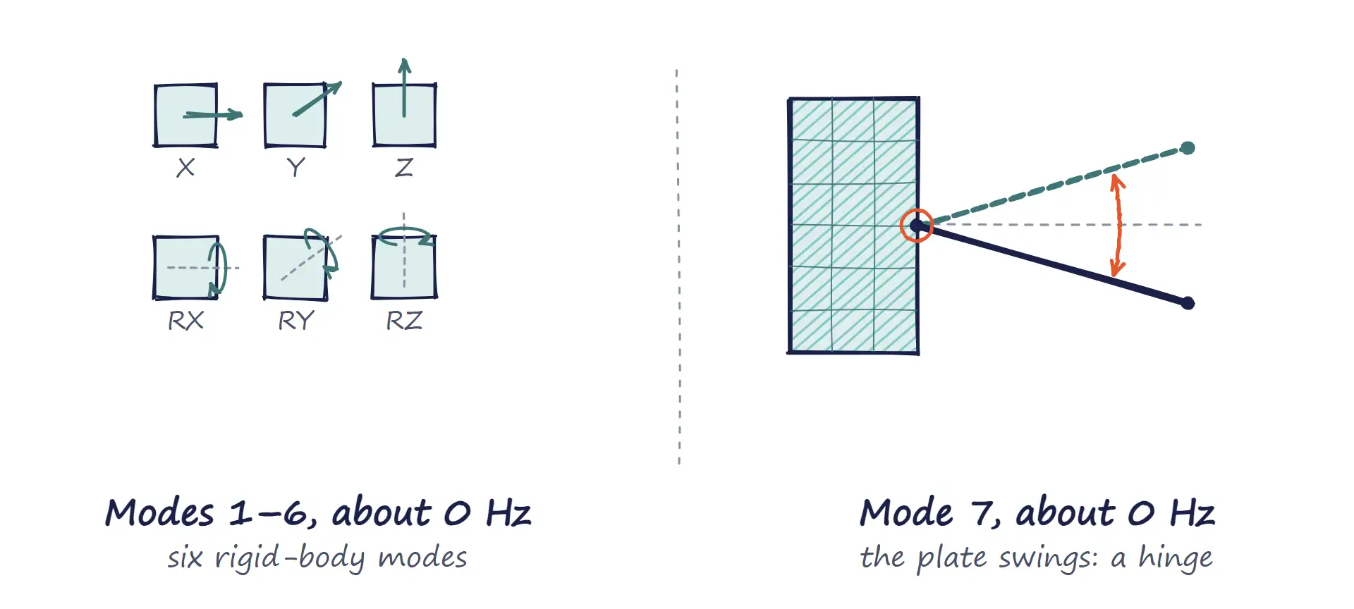
Figure 3: In a free-free modal run, a connected structure has six rigid-body modes near 0 Hz. A seventh one points to a joint that acts as a hinge.
The free-free run catches a hinge that lets a part swing. The other case from the start of the post, a plate that is also held somewhere else (for example along another edge), gives no extra mode and no warning: the hinge just makes the joint too flexible. So also look at the deformed shape under load: a plate that kinks sharply at a joint is the same problem.
When a connection type is new to you, try it on a small test model first, for example a plate glued to a block, and compare it with a hand calculation. Once the joints work as intended, the next question is whether the mesh is fine enough, which we cover in the mesh convergence section of our FEA guide.
We hope your next shell-to-solid joint behaves on the first run.
Sources: the Simcenter Femap 2606 Commands Guide and the Simcenter Nastran User’s Guide (modelling guidelines, model verification, gluing).