
Simcenter STAR-CCM+ version 2606 was released on 1st of July, and this version was packed with great new features for CAD and meshing. In this week’s blog post we are therefore taking a closer look at the highlights for pre-processing. Starting with some deep dives, moving on to honorable mentions and then even a description of a bonus mention.
And don’t miss the previous Volupe blog post about multiphase features:
https://volupe.com/simcenter-star-ccm/simcenter-star-ccm-2606-multiphase-news/.
Search for piercing faces in 3D-CAD
The first feature we will dive into deep is the new 3D-CAD feature that will help you detect problematic faces in an as early stage as possible. Pierced faces, when two faces are crossing each other (or overlaps or coincides), are not acceptable when creating the mesh. Therefore, it is great that we, now in version 2606, can detect this problem already when working with the CAD using the search condition “Clash – (face pair) – is – piercing”. Previously, Surface repair was the best way of detecting piercing surfaces, but since 3D-CAD is part of the pipelined workflow it is from now on beneficial to stay within 3D-CAD for this type of geometry-handling.
In the video below you see how to use the search tool and set the conditions in order to show all pierced faces. The imprint operation at the end of the video shows one way of solving faces crossing each other. Note that if the faces are of very low quality they might need to be re-created.
Cylindrical template for trim cell mesher
Let’s have a look at the new cylindrical template in the mesh operation for trim cells. Trim cells are great in terms of cell quality and numerical accuracy, but for round objects (like discs or cylinders) the trimmed cells can become problematic. Problems that can decrease the numerical accuracy are for example stair stepping (when the cubic cell corners are cut and rounded by the edge) or flow that is not aligned with the cell face normal for rotating regions.
In the left picture you see a trim cell mesh for a disc (top view). In the right picture you see how the cylindrical template creates the mesh in order to increase the cell quality and provide rotating simulations with a directed-mesher-like outcome for maximum numerical accuracy.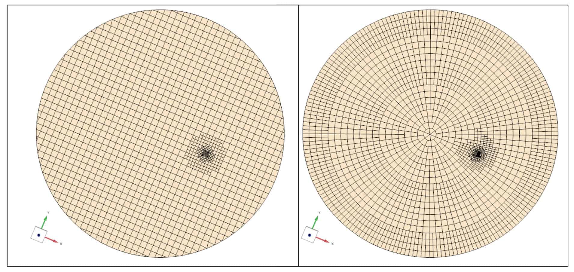
You set up the cylinder mesh template in the Trimmed cell mesher node in the mesher folder for your automated mesh operation, see picture below. There are less default controls available than for the original automated mesh operation (for example is Volume growth rate not included), and the template itself runs in serial mode as well. There will therefore, most probably, be updates for this new feature in the future – like including more setting and compatibility with AMR etc.
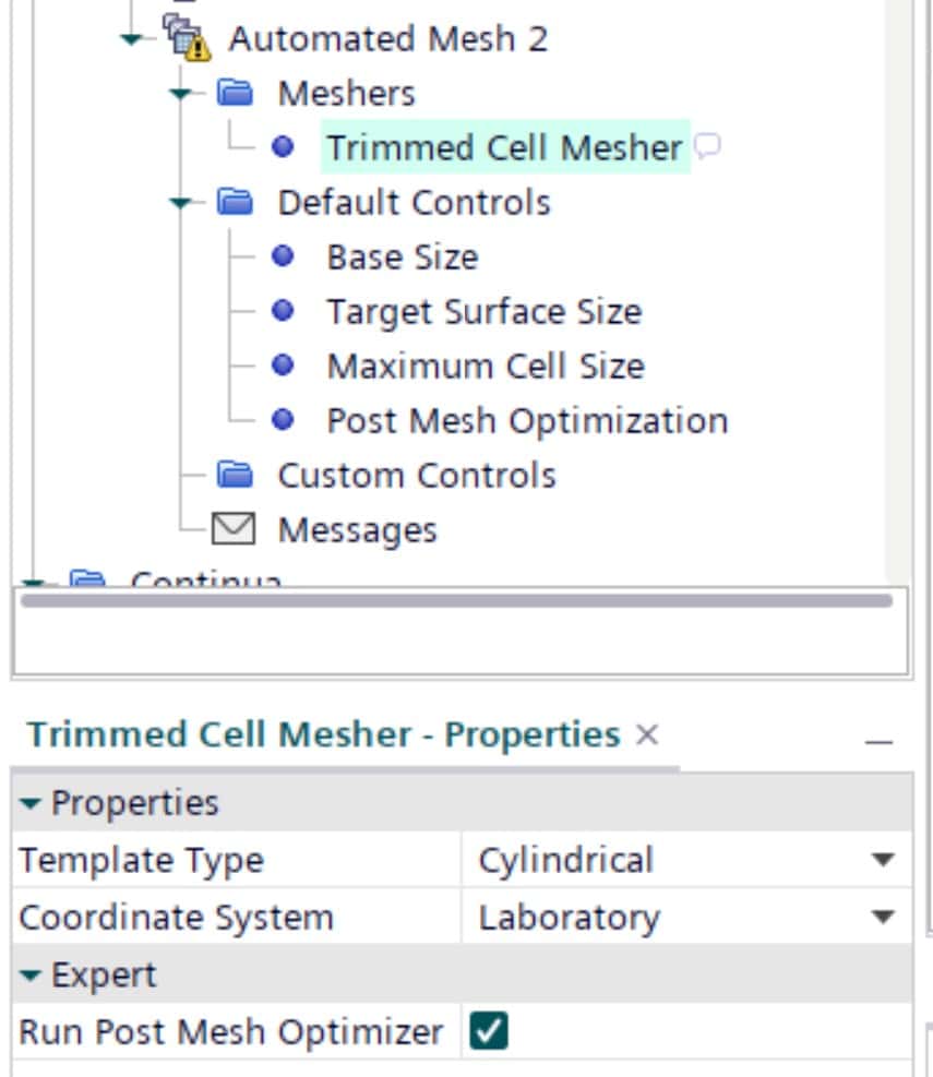
When setting up the cylinder mesh you need to specify a z-axis in a coordinate system in order to know in which direction the mesh should turn. This z-axis can also be specified in a local Cartesian coordinate system.
Note: the template will generate more cells than in simulation using only trimmed cells, since the aspect ratio can never be as optimal as when using cubic cells. This is another reason why the mesh generation can take some extra time, but you will gain that in numerical accuracy instead. The accuracy will show in terms of smoother and faster decaying residuals, and non-smeared velocity gradients.
Message output log for mesh operation
Another great new feature for your automated mesh operation is the Message folder. The message folder is added to provide information about where problems occurred in your mesh generation. The message turns red, as seen in the video below, when an error occurred during the meshing. The checks that are performed are validity for all surfaces in the surface remesher and for the volume mesher. Therefore, the type of information you will receive is locations where error has occurred for these surfaces.
Getting this information already helps a lot, since you done have to search for coordinates in the output window, create probe points and then start the investigation on how to solve the problem. The list of errors also arrives with a connection to Surface repair so you can enter the reparation stage and edit the problematic surfaces directly. The problematic area is visualized by a sphere to indicate within which volume to search for the error.
Honorable mentions
There are several more useful features when it comes to pre-processing in the newest release. Some of them are mentioned in this chapter, and hopefully they will improve and speed up your everyday simulations.
Direct weak contact possibility for Boolean operations:
For the Boolean operations subtract, unite and intersect there is now an expert property to enable – creating weak contact together with the operation. This automatically creates a contact between your parts and can therefore be used instead of creating and using an imprint operation. Since the weak contacts are not automatically supporting conformal meshes the imprint operation is still needed if you desire conformal interfaces.
Partial surface wrapping compatible with parallel surface wrapping:
The partial surface wrapping is now compatible with parallel surface wrapping, giving that the need for using the legacy wrapper is significantly smaller. We recommend using the new surface wrapper, as described in this previous blog post:
https://volupe.com/simcenter-star-ccm/new-features-for-cad-and-mesh-in-simcenter-star-ccm-2506/
Grouping of mesh operations:
To organize and keep better structure of your mesh operations you now have the possibility to group and move operations. Right-clicking to group or ungroup can make the operation structure easier to handle, especially if you have many operations in your simulation.
Bonus mention
This feature is actually announced as a FSI (fluid-solid-interaction) feature, but it is also a preprocessing operation which might come in handy for more types of simulations than only FSI.
Surface from Volume mesh operation:
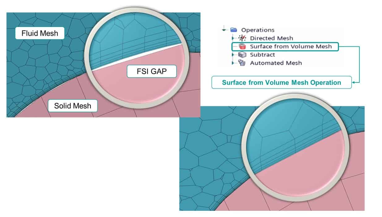
The new operation Surface from volume mesh makes sure that there are no gaps between meshes from different operations. In FSI (and perhaps in other moving mesh) simulations it can be useful to guide a surface back to the discretized representation of the region on the other side of the interface. When the connection between breaks and gaps are introduced the interface and mesh quality cannot be guaranteed. With this new feature Simcenter STAR-CCM+ can unsure a gap free discretization even for non-stationary meshes.
We at Volupe hope that this blog post has been of great interest and that you will download the new version of Simcenter STAR-CCM+ to use these handy features. If you have any questions, feel free to reach out to us at support@volupe.com.
Author
Christoffer Johansson, M.Sc.
support@volupe.com
+46764479945